Double check my circuit is wired safely

Homebrew Talk - Beer, Wine, Mead, & Cider Brewing Discussion Forum

Help Support Homebrew Talk - Beer, Wine, Mead, & Cider Brewing Discussion Forum:

This site may earn a commission from merchant affiliate links, including eBay, Amazon, and others.

blackheart

Well-Known Member
Joined
May 4, 2008
Messages
315
Reaction score
19
Location
Binghamton, NY
I am working on building an automated brewing system. This consists of multiple 120 and 24v AC pumps and valves. I have a prototype built and working but its time to move on to a solid and robust design.

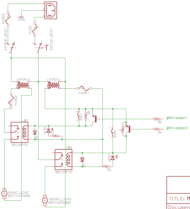
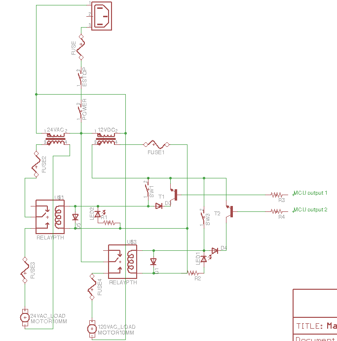
I have drawn a basic circuit diagram showing the flow of both 120v AC and 24v AC through the system to power two loads via relays. The relays can be triggered by either a manual switch, or, a transistor via a micro controller. The relays are ground triggered and I have added a diode to protect the transistor/microcontroller in the case that the manual switch is flipped, no current will get back to the microcontrollers inputs.

I have also added a diode over the relay coil so when the magnetic field collapses everything is protected. There are fuses at numerous points throughout the circuit to protect the various parts. The picture of the 12v DC coil is ment to represent a 12v DC power supply, which would be a separate product.

To operate the circuit, you would turn on both the E-stop switch and power switch. Pressing either switch connected to a relay will both trigger that relay and send voltage to the load connected to it. It will also light a LED to signal that it has been activated. Alternately, the microcontroller could send a 5v signal to the transistor to trigger the relay.

My questions are the following

1) Does this circuit design look safe to you?
2) Have I placed fuses in the appropriate locations?
3) Have I protected my relays, and microcontrollers with diodes correctly?
mastercircuit.png


Currently I have something very similar to this design up and running, however it has no fuses or diodes, and I have not tested the microcontrollers ability to control it due to safety concerns for the MC. Thanks for your help!
 
I am working on building an automated brewing system. This consists of multiple 120 and 24v AC pumps and valves. I have a prototype built and working but its time to move on to a solid and robust design.

I have drawn a basic circuit diagram showing the flow of both 120v AC and 24v AC through the system to power two loads via relays. The relays can be triggered by either a manual switch, or, a transistor via a micro controller. The relays are ground triggered and I have added a diode to protect the transistor/microcontroller in the case that the manual switch is flipped, no current will get back to the microcontrollers inputs.

I have also added a diode over the relay coil so when the magnetic field collapses everything is protected. There are fuses at numerous points throughout the circuit to protect the various parts. The picture of the 12v DC coil is ment to represent a 12v DC power supply, which would be a separate product.

To operate the circuit, you would turn on both the E-stop switch and power switch. Pressing either switch connected to a relay will both trigger that relay and send voltage to the load connected to it. It will also light a LED to signal that it has been activated. Alternately, the microcontroller could send a 5v signal to the transistor to trigger the relay.

My questions are the following

1) Does this circuit design look safe to you?
2) Have I placed fuses in the appropriate locations?
3) Have I protected my relays, and microcontrollers with diodes correctly?

mastercircuit.png


Currently I have something very similar to this design up and running, however it has no fuses or diodes, and I have not tested the microcontrollers ability to control it due to safety concerns for the MC. Thanks for your help!

The circuit looks safe and functional. I have just a few comments.

  • You don't need fuse3, the motor is already protected by fuse2.
  • It is up to you, but I would ditch the power switch. The E-stop does the very same thing, unless there is a location issue.
  • Diodes D3 and D4 are not needed. You can keep them if you like but they do not protect the transistors nor the MCU.
  • It is a good idea to have a resistor between the base and the emitter of each transistor. Make it 5-10x the input resistor, R3 and R4. This will help ensure that the transistors shut off completely or else they could heat up.
 
Thanks for the reply. So we dont need to fuse each pump/valve individually as long as their is the fuse further up before the supply.

We could use one of those nice e stop buttons as the single power switch.

One of our main concerns is to protect the microcontroller and prevent it from damage if we are using both manual control and the MCU at the same time. I've never heard of adding a resistor to the transistor before. You're saying, add it to the emitter and collector just like the diode on the relays?
 
You're saying, add it to the emitter and collector just like the diode on the relays?

Not quite, but between the base and emitter. As bipolar transistors heat up they tend to leak a little current from the collector in to the base. This will then turn on the transistor a little, but not enough to pull the collector voltage to ground. This causes heating of the transistor, which then leaks more current, and we have a thermal 'avalanche' going on. The base-emitter resistor also helps to shut off the transistor in case the MCU does not output exactly zero volts, again causing leakage in the transistor.

Here are two rules of thumb when designing bipolar transistor switches.
  • Use 1/10 of the collector current to drive the base.
  • Bleed 1/10 of the base current to ground because of the two issues I discussed above.
 
Looking for circuit breakers. Drawing about 10A max with everything on, which would never be the case. 12vDC is 3A and 24v AC is rated up to 10A but is only ever drawing 1-2A

Here is a 10A dual pole circuit breaker... we would connect the Hot and Neutral wires into one each.

http://www.automationdirect.com/adc...Series)/C_Curve_(0.5A-40A,_WMZT2Cxx)/WMZT2C10

Stil not sure what C curve and D curve is, if 10A is the right rating, and if we need additional breakers for the 24v AC and the 12v DC.
 
Looking for circuit breakers.

Here is a 10A dual pole circuit breaker... we would connect the Hot and Neutral wires into one each.

http://www.automationdirect.com/adc...Series)/C_Curve_(0.5A-40A,_WMZT2Cxx)/WMZT2C10

Stil not sure what C curve and D curve is, if 10A is the right rating, and if we need additional breakers for the 24v AC and the 12v DC.

First of all, a dual pole breaker is for the two hot lines of a 240V circuit. For 120V you'd use single-pole.

Secondly, the breakers here are much less expensive:

http://www.factorymation.com/s.nl/it.A/id.5698/.f?sc=2&category=15748
 
OK. So I was told to fuse both the Hot and Neutral lines if possible.... Also should I be fusing the 12v DC and 24v AC lines? If so, then I know their is a fuse for 24v.... but what about 12v DC?
 
OK. So I was told to fuse both the Hot and Neutral lines if possible.... Also should I be fusing the 12v DC and 24v AC lines? If so, then I know their is a fuse for 24v.... but what about 12v DC?

Well, it certainly never hurts to protect a circuit! The D-curve breakers on the site I referenced would be fine for your 24V motor. If you want a breaker for your 12V circuit, you'd use one of the B-curve units. You could also just use a simple in-line fuse holder from Radio Shack for either. The automotive blade style (ATC, ATO) fuses are good to at least 24V (many boats use 24V systems, for example). The only issue I see there is you may want to select a "slow-blow" style for the 24V since it's a motor.
 
Sorry if I am repeating myself here but I want to be exact so I can place an order and dont have to reorder later.

120v, 10A max draw I can get the Dual Pole 10A D-curve breaker and connect both the Hot and Neutral wires to it. This is the one you recommended.
http://www.factorymation.com/s.nl/it.A/id.5698/.f?sc=2&category=15748

24v AC 2A max draw from the 2x gas valves, I need a 2A breaker for just the hot side. Like this one.
http://www.factorymation.com/s.nl/it.A/id.5681/.f?sc=2&category=15748

And for the DC 3A PSU I need a 3A B curve breaker like this one.
http://www.factorymation.com/s.nl/it.A/id.5669/.f?sc=2&category=15747

I know I could use a fuse, but if I am already putting in a DIN rail with 3x breakers, might as well make it 4....They have a nice 10cm DIN rail for $1 that looks like it will work nicely.
http://www.factorymation.com/s.nl/it.A/id.60442/.f?sc=2&category=21332

All of the valves and electronics are on 12v so I want it fast acting. Just 2 gas valves are on the 24v line.
 
I posted the link to the 2-pole breaker because it was the equivalent (but less-expensive) product to the one you had listed. You really only need a single pole breaker for the 120v line. Aside from that, it looks pretty good to me.
 

Latest posts

Back
Top