AG Monster

Homebrew Talk - Beer, Wine, Mead, & Cider Brewing Discussion Forum

Help Support Homebrew Talk - Beer, Wine, Mead, & Cider Brewing Discussion Forum:

This site may earn a commission from merchant affiliate links, including eBay, Amazon, and others.

natehilde

Well-Known Member
Joined
Nov 3, 2006
Messages
100
Reaction score
8
Location
Colorado
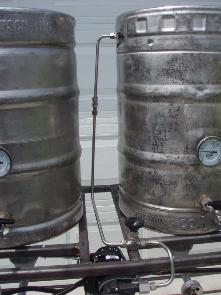
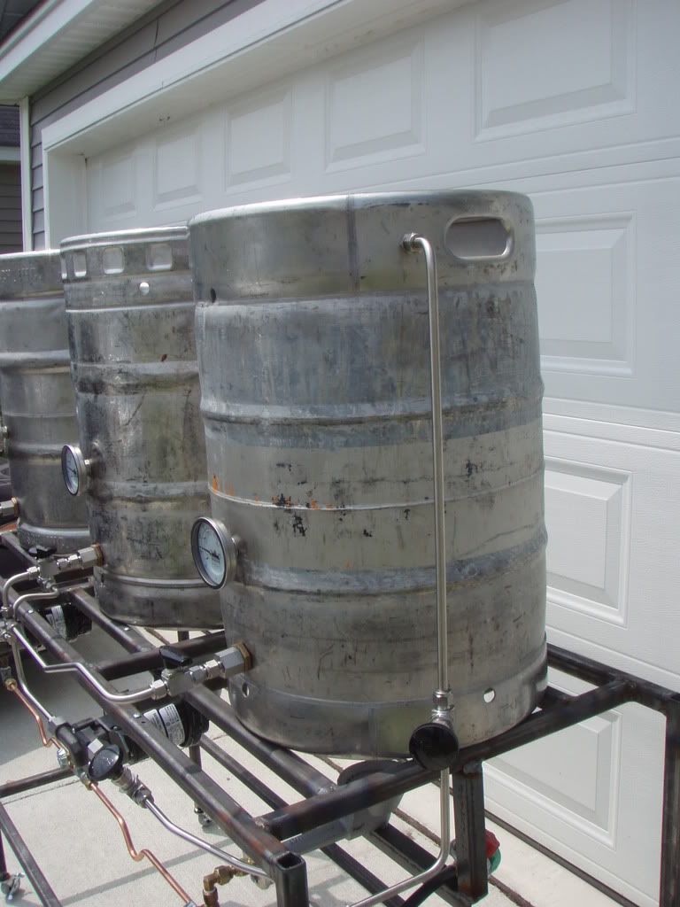
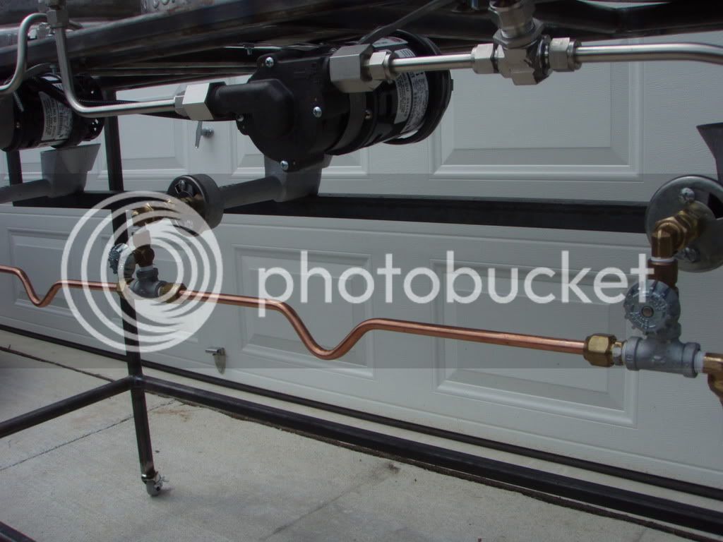
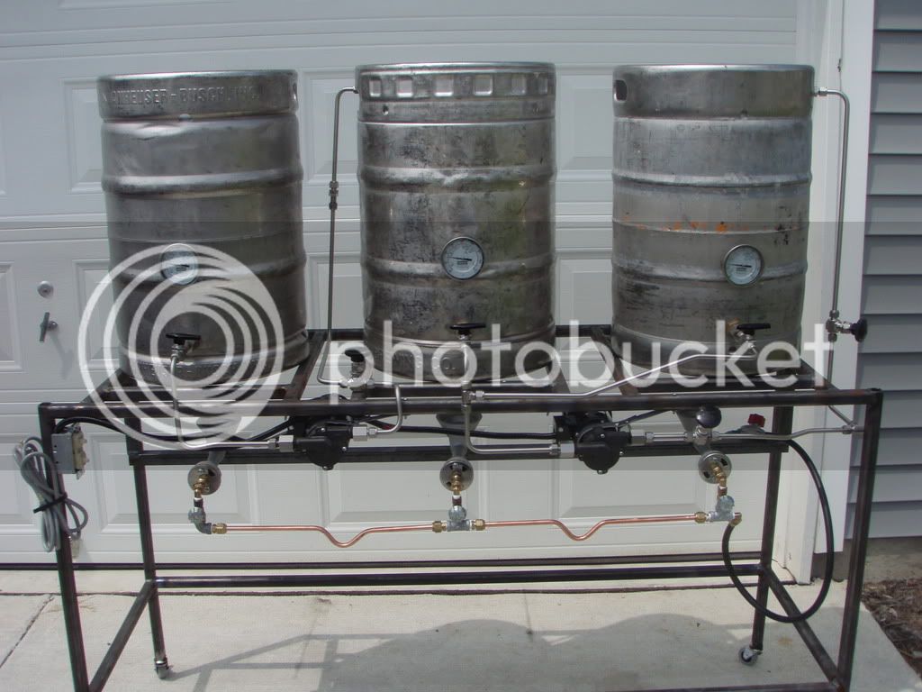
I just thought that I would let you all know that construction of the AG Monster is underway. It is a triple vessel, triple burner, dual pump, CF heat exchanger brewing machine. Frame welding will commence this weekend. Pictures and details to follow.

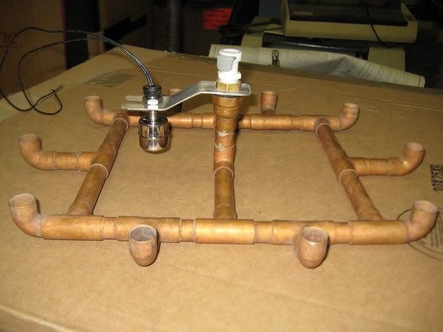
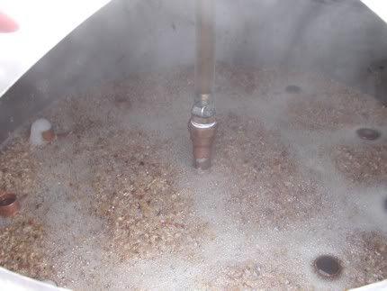
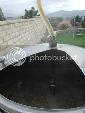
I am confused, however, on how exactly to construct the sparging device. I have never seen one in operation. Is there a specific height that it must be away from the grain bed? What do you recommend?

Thanks
Nate
 
I've seen some sparge arms that are right above the grain, and some that sit on the grain and percolate the water through up-turned outlets. Honestly, I don't think it really matters as long as you allow the water to "gently" sprinkle onto the grain.

Now, you called it an "AG Monster". Monster would imply big/large/huge. How big are we talking?

2 pumps - are you going w/ a single tier design?
 
Thanks for the input. What I have in mind right now for the sparging rig is basically a circular shaped copper manifold with small holes drilled incrementally along its inside and outside diameter. Will that serve the purpose?


AG Monster will be something like this, except I will run all copper tubing from vessels to the pumps. All valves and pump powers switches will be mounted on a valve board extending out from the front of the frame. Similar to a desk. I just hope that the resulting headloss from all the tubing bends and elbows won't adversely affect the flow rate. Additionally, I don't have the cash for the thermostatic regulators yet, but can add them later. What do you guys think? I am looking for any ideas that might better improve my design.
View attachment 1850
 
Looks like you're on the right track. Keep us posted w/ some pics as you make progress. You should have a nice rig when it's all done!
 
I built a bubbler type manifold because grains will not clog it. I can switch from recirculation to sparging by just turning a ball valve.

I just added a float switch to it so the water level stays at the same height as the bubbler when sparging.
IMG_0174.jpg


Sparge5.jpg
 
Well, that is something that I had never even considered. That is pretty cool. I had planned doing the same with sparge/recirculation ball valve isolations. So, from the pictures, it looks like the only thing that is supporting your bubbler is the tygon hose that is supplying it. Is that the case? Additionally, I guess that it is imperative that the height of the sparging rig, relative to the grain bed, is adjustable. Is that a safe assumption?

Thanks for the ideas.
 
I run it through a fitting in the lid and use a hose clamp to hold it in place. I use a QD to make it easy to remove and clean.
Recirc1.jpg


Sparge3.jpg
 
That looks like a very sweet operation you're running there. I especially like the sliding lid design. Thanks for the pics.


Just thought I'd let you all know that I just finished in the garage with the first nights construction. I have been "playing" with my new toy. I went to Lowes and got a 14" chop saw to cut the square tubing for the AG Monster's frame. That thing is the poopy. There is something very manly and cool about cutting and fusing metal. It makes me feel powerful!! Anyway, I have cut all the pieces for the frame. I am now in the process of cleaning and beveling the ends of the tubing in preparation for welding tomorrow. As long as SWMBO has nothing for me, I should have the frame tacked and welded tomorrow. I will post some in process and finished product pics tomorrow.
 
Monster Mash said:

How does the sparge water flow evenly out of all the out of all the openings? In the pick it looks like its mainly coming out of one on the left? Sorry if this is a dumb question, just looks that way to me - like the water flows out of the lowest outlet because its not perfectly level? But actually it looks like the ones on the right are lower in the grain....what's going on?
 
Looking pretty good, I really need to learn to weld, you can only build so much out of wood.

Cheers
 
i was just thinking looking at those pictures, "damm i wish i was still in high school welding class" lol access to MIG, Stick and Tig welders, plasma cuters, cut offs, cutting torches, pipe benders, grinders metal laths. and all i did was make a bumper for my jeep and smoke pot in the metal yard lol. well i didnt brew beer back then but you know :)
 
Lil' Sparky said:
I think you're a better welder than photographer. :D
"It was at a funny angle" (British Accent)

wop31 Looking pretty good, I really need to learn to weld, you can only build so much out of wood.
Fusing metal together is easy. Making the weld look good is the hard part

"damm i wish i was still in high school welding class" lol access to MIG, Stick and Tig welders, plasma cuters, cut offs, cutting torches, pipe benders, grinders metal laths.
Much to the dismay of SWMBO, I just buy the tools I need when I need them.
 
I didn't have much time to work on the Monster this weekend, but I still managed to get the cut edges on the kettles ground smooth and the kettles cleaned. I also managed to get the thermometers, bulkhead fittings and ball valves mounted.

http://i201.photobucket.com/albums/aa29/natehilde/P6241421.jpg
http://i201.photobucket.com/albums/aa29/natehilde/P6241423.jpg

This week will be the tedious process of bending and routing all the SS tubing. I am also going to try to get the pumps wired into toggle switches and mount the burners in the proper position. That being said, I can do fluid transfer systems all day long, but electrons confuse the hell out of me. On these pumps, I have three wires. I want to connect the pumps to individual toggle switches. The switches that I have seen have only two lugs. What do I do with the other wire.

Thanks
Nate
 
natehilde said:
On these pumps, I have three wires. I want to connect the pumps to individual toggle switches. The switches that I have seen have only two lugs. What do I do with the other wire.

Here is a pretty decent how-to guide to installing a simple light switch, which would be the same setup as your pumps (in the diagrams replace the bulb with your pump). The third wire, most likely green, is a grounding wire which is there ultimately for your saftey. If anything inside the motor or switch was to be short circuited the electricity would travel safely through the ground wire and not be as dangerous as an ungrounded setup. You can also do a google search for other similar guides, the nets are full of them.

Your project is looking great so far, the frame seems very robust :mug:.
 
Lookin' good. I really like the single-tier designs. I haven't figured out why everyone builds them so high though. I would want mine a little lower if I built one.

[nitpick]It appears that you put the supports very close to the edges of the kegs. You'll have to be careful that an edge doesn't slip off of one of the supports. With some weight in the kegs they won't be moving around much, though. When I built mine, I put 10" between the supports to give plenty of wiggle room. [/nitpick]
 
Put some casters on it so you can roll it around with ease. Also I would make a little lip on the top rail to keep the kegs in place.
 
TheFlyingBeer said:
Here is a pretty decent how-to guide to installing a simple light switch, which would be the same setup as your pumps (in the diagrams replace the bulb with your pump).

Thanks. That helps. Like I said before, pumps and valves all day, but that "tron-magic" stuff freaks me out!!!

Lil' Sparky said:
Lookin' good. I really like the single-tier designs. I haven't figured out why everyone builds them so high though. I would want mine a little lower if I built one.

[nitpick]It appears that you put the supports very close to the edges of the kegs. You'll have to be careful that an edge doesn't slip off of one of the supports. With some weight in the kegs they won't be moving around much, though. When I built mine, I put 10" between the supports to give plenty of wiggle room. [/nitpick]

I built mine up just high enough that I can store thing under when not in use. It is low enough that I can still look inside without standing on anything. As for the supports under the keg, that was a design flaw on my part. two of the supports on each keg are too far apart, but I mitigated the problem by putting the other two supports close enough to to provide adequate support. I am still going to add a piece of angle iron on the back of the frame. This is to prevent the kegs from moving around too much.

BlackZX3 said:
Put some casters on it so you can roll it around with ease.

That is absolutely on the list of things to do. I just haven't looked around for the ones that I want yet. I know I want them to be locking.


Thanks so much for the input and ideas. All the help that you guys have given me has been outstanding!
Nate:mug:
 
Another progress update on Monster.

I managed to get the burners mounted last weekend. I still have to get pipe routed to each of them.

I found a way to mount the pumps last weekend. In the plumbing section at the hardware store, I found some 2 and 3 inch pipe mounting brackets. I had to modify them somewhat to allow the pump to fit securely inside them. I drilled through the frame and bolted the brackets to the underside of the frame. They seem to do the trick. I also got them wired up to a switch and op tested them. I run like a champ.
http://i201.photobucket.com/albums/aa29/natehilde/P7061459.jpg
I also purchased a tubing bender and have been routing 3/8" SS tubing between the pumps and kettles. That has been an interesting challenge. SS tubing is very hard to bend. When it is all finished, it should look pretty good though.
http://i201.photobucket.com/albums/aa29/natehilde/P7061461.jpg
I noticed that after I routed and attached the tubing to my pumps They seem much more stable. Any doubt that I had about the mounting brackets not working out is gone now.

I decided to go with a bazooka tee in my MLT and Kettle. I will probably have to modify them some to ensure I get the best suction possible.
http://i201.photobucket.com/albums/aa29/natehilde/P7061462.jpg

On a side note, I learned a valuable lesson during this process. I'm sure you will give me a hard time about this one, but here goes. NEVER WELD IN SHORTS AND A T-SHIRT. THE "SUNBURN" IS HORRIBLE!!!!
http://i201.photobucket.com/albums/aa29/natehilde/P6181416.jpg
 
The "Monster" is looking good but I worry that your March pump is too close to the burners. Can you add a shield of some sort to protect it from the heat. I have the same burners on my rig and things as close as 1 foot get pretty flippin' hot. Just an observation that I thought I'd pass along from my setup. Keep more pics coming.
 
I appreciate your suggestion about the heat shield. I have been worrying about the same thing. I have looked at a few places for preformed heat shields with no success. Since so many of the components on this system are in close proximity to the burners, I want heat shields that have a low thermal conductivity and high corrosion resistance. It would also be nice to raise the efficiency of the system by being able to direct more heat toward the bottom of the vessels. If anyone has any ideas for heat shields or heat shield material, they would be greatly appreciated.

Here is Saturday morning progress. More tubing routed and assembled. I have a game tonight and won't be able to get much more done until tomorrow. I will give another update tomorrow evening.
http://i201.photobucket.com/albums/aa29/natehilde/P7071463.jpg
http://i201.photobucket.com/albums/aa29/natehilde/P7071464.jpg
http://i201.photobucket.com/albums/aa29/natehilde/P7071465.jpg
http://i201.photobucket.com/albums/aa29/natehilde/P7071466.jpg
 
Won't burn, melt, deform, or pass much heat? Hmmmmm, about the only material I can think of is some ceramics. Check out your local Home Depot or equivalent and see if they have any tiles that can take the heat. Or if you don't mind the added weight, bricks will do the job quite nicely.

Hope that helps!
 
Yeah I had thought about ceramic as well. Maybe I will continue down that route if no other solution presents itself.

Thanks
 
dude, that is sexy!

I love the bent tubing porn!!!!!!

(I'm a gearhead, I get off on this stuff!)
 
That part of this project has really been a challenge. Some of it doesn't look perfect, but it will do the trick. I just hope that the throttle valves I got will provide an adequate flow rate.
 
More progress. It has been slow going for the last two weeks. I really need to get this finished, I ran out of my last brew a week ago. I am going to get some of Ed Wort's Apfelwein in the fermenter tomorrow, but I still want to put some ale yeast to work!!

I finished installing the liquid transfer tubing. You will notice that there are a few more valves installed. I also finished installing the gas transfer tubing. Originally, I was going to install pipe, but tubing is a little more forgiving and still gets the job done.
In these pictures, you can see the path for the sparge water to flow from the HLT to the MLT. I installed a fitting at the top of the MLT so that removal of the sparge arm will be easy.
P7211471.jpg

http://i201.photobucket.com/albums/aa29/natehilde/P7211472.jpg

Here you can see the path for wort to flow in two different directions. Using the second pump, I will transfer wort from the MLT to the boil kettle and from the boil kettle to the CFC. I also install a fitting at the top of the boil kettle for a fill tube that runs to the bottom of the boil kettle.
P7211473.jpg

http://i201.photobucket.com/albums/aa29/natehilde/P7211474.jpg

Here are all the gas connections and tubing. This part was fun!! I love playing the fitting game. (sarcasm) It took me an hour to find all of these fittings at the hardware store. It does look pretty sexy though. You will see that there are bends in the gas tubing. These are to ensure that the tubing has room to expand if it gets hot. That will prevent the fittings from leaking which could be very bad!!!
http://i201.photobucket.com/albums/aa29/natehilde/P7211475.jpg
http://i201.photobucket.com/albums/aa29/natehilde/P7211476.jpg
P7211477.jpg


Here is what it looks like so far. I still am trying to work through the heat shield problem, but it is almost finished. Once I have it completely assembled, I will take it all apart and paint the frame.
P7211478.jpg

Constructive criticism is welcome!!!
 
Looking good. You've definately put some time into that bad boy.

FYI, when you want to include an image in your post, you can use the following format with the spaces removed. It takes the work out of seeing the pics you've put on photobucket.

[ img ]URL[ /img ]
 
Lil' Sparky said:
Looking good. You've definately put some time into that bad boy.

FYI, when you want to include an image in your post, you can use the following format with the spaces removed. It takes the work out of seeing the pics you've put on photobucket.

[ img ]URL[ /img ]
Thanks for the compliment and the computer tutorial. I wondered how the hell people did that.
 
Your work is very neat. However, I see several problems. March pumps are not self-priming. The pumps should be mounted as low as possible, i.e., about 2-3 feet lower. The other problem with your pump location is that they are way too close to your burners. One other potential problems is that your flow may be quite limited with 3/8" ID tubing, especially on the input side of the pump.
 
stevehaun said:
Your work is very neat. However, I see several problems. March pumps are not self-priming. The pumps should be mounted as low as possible, i.e., about 2-3 feet lower. The other problem with your pump location is that they are way too close to your burners. One other potential problems is that your flow may be quite limited with 3/8" ID tubing, especially on the input side of the pump.
Thank you for your input. I realize that any centrifugal pump is not going to be self-priming. I decided on this location for the pumps as modeled after the more beer brew sculpture. I personally have not done the math to determine the Net Positive Suction Head available versus the Net Positive Suction Head required. This is for no other reason than that I have not been able to find the technical data for the pumps. I believe that the only time that I may encounter a problem with inlet flowrate is when pumping at the bottom of a vessel. I agree that the pumps are probably mounted too close to the burners, and I am working on pump and burner heat shields. If you have any recommended solutions, I am all ears/eyes.
Thanks again.
 
Cool looking setup! I just got my "Brewflex" system far enough along this past weekend to actually give it a whirl and it was my first time to use a pump in this manner. I was more than a little surprised at how tricky it was to prime. I mounted mine roughly 1 foot below my lowest kettle, and it was definitely a chore to prime from that level (easy going from the upper level tho).

I ordered another stainless tee fitting yesterday that I'm going to come back in and mount just above the "out" port on the pump. I'll hang a valve off of it to open up and let air bleed out to prime and see if that makes it any easier... I've read a few references that indicate that helps, but haven't tried it yet so take that suggestion with a grain of salt!

Good luck!
 
in that last picture, from left to right, what are the names of each keggle-device? i know MLT stands for mash lauder tun, but other then that... completely lost.

looks great though!
 
I'm going to guess that from left to right you've got your hot liquor tank (HLT) which feeds hot sparge water to the MLT in the middle, out of which flows the sugary wort to the boil kettle on the right.
 
then why is there a re-circulation mechinism worked up with the tank on the right? that led me to believe that was the mash tun, but it didnt make sense being on the right
 
The line on the far right just allows me to run off from the MLT to the BK while sparging at the same time. That's all it is.

I just wanted to give a big thanks to stevehaun for the word of advice on pump location. I did some theory-to-practice on the pumps last night. Sure enough, I lost suction at the keg outlet level. There is not enough suction head for the march 809 to operate at the current location. I am going to have to order more tubing and relocate the pumps to much lower on the stand. It is a bummer that I will have to re-work all of that, but I guess it is better to find out now. Additionally, this also solves the heat shield problem!! Two steps forward, one step back.

I'm used to it, I'm in the NAVY!!
HOOYAH!!!
 
Back
Top