SSRs are for Chumps

Homebrew Talk - Beer, Wine, Mead, & Cider Brewing Discussion Forum

Help Support Homebrew Talk - Beer, Wine, Mead, & Cider Brewing Discussion Forum:

This site may earn a commission from merchant affiliate links, including eBay, Amazon, and others.

craley1

Member
Joined
Jul 29, 2010
Messages
14
Reaction score
0
Location
St. Louis
So I'm not real thrilled with the prospect of installing a bunch of SSRs with huge heat sinks in an already small electrical box. The alternative I have found is a Miniature Power Relay. Here is a link.

The main disadvantage I can see is that because it is not a solid state unit, the number of operations are limited to 100,000 at their rated current. I figure if these were used once a week, they could potentially need to be replaced after a year and a half.

Has anyone used these instead of SSRs? Are there any other options to SSRs that are cost effective (contactors don't appear to be very cheap).
 
If you're using it as a temp controller, you're fine. If you want to use a PID in manual mode for effective 50% power output for instance, you're looking at burning it up in 50,000 seconds of use.
 
Yep...

Mechanical relays aren't designed to be switched on and off every 2 seconds.

Not that it won't work, but it's outside the spec.

OTOH, they are cheaper than SSRs...

100,000 cycles/2 per second = 50,000 seconds = 833 minutes = 13.8 hours of element control. That's about 10 batches of beer - Less if you are using it for sparge water and boiling.
100,000 is MTBF too, it could be less or more...
 
Thanks for the feedback. That's what I was afraid of. Are there any other solutions available, something I haven't mentioned? Or is there an SSR that has a smaller footprint?

Also, back to the power relays: what about for the pumps? Once they start pumping, they stay on until their process is complete, correct? That would at least reduce the space requirements for two of the SSRs (assuming 2 SPST SSRs for each 240v heater element and 4 heaters and two more SPST SSRs/power relays for the pumps).

They will work fine for the pumps - Provided they are rated for the pump's current draw (Buy you knew that already)

SSRs are around because a solid state switch MTBF is far higher than a mechanical equivalent.

I'm installing 2 enclosures in my rig for this very reason. One will house all of the high voltage stuff - Contactors, relays, and distribution stuff. The "Low voltage" panel will have things like the SSR/relay trigger signals feeding back to the "High voltage" panel.

May not be an option for you, but it's there.

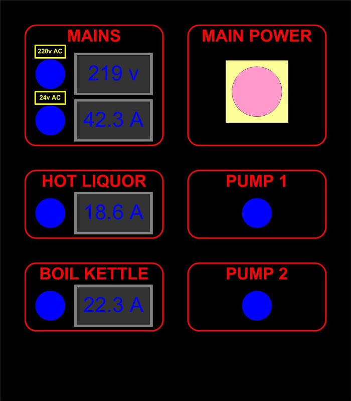
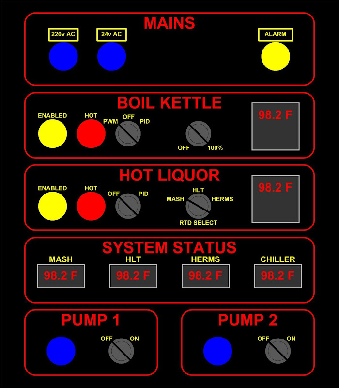
Mine looks like this:
Schematic

High Voltage panel:
HV%20Panel.jpg


Low voltage panel:
LV%20Panel.jpg
 
Mine looks like this:
Schematic

Wow. That's an impressive set up. I like your idea and had considered two separate compartments/panels for all the electrical.

I'm going to go a little off my topic: why do you have contactors and SSRs in series on your heaters? Wouldn't two SPST (or one DPST) SSRs alone work?
 
Wow. That's an impressive set up. I like your idea and had considered two separate compartments/panels for all the electrical.

I'm going to go a little off my topic: why do you have contactors and SSRs in series on your heaters? Wouldn't two SPST (or one DPST) SSRs alone work?

Theoretically yes,
But SSRs have a bad habit of "Failing closed", and the contactors give me a failsafe to know that there is no way power is getting to the elements.
I could just use really big switches, but it's designed so that when I want to go to full automation I just have to trigger low voltage signals to the elements and pumps. IOW replace the switches in the low voltage panel with a BCS or similar, install solenoid valves in place of the ball valves, and off we go.
It also allows me to install interlocks like a float switch or temperature interlock inline with the contactor trigger. It's easier to get a float switch that can handle 24 volts than 240 volts @ 25 amps ;)
 
Is there any issue with switching an RTD line? Less sensitive to noise than a thermocouple?

I haven't built it yet :D

It was an afterthought really - That's why it's not in the schematic.

I was designing the panel with temp sensors everywhere, and thought "How cool would it be to switch the RTD input for the mash PID?"
 
Is there any issue with switching an RTD line? Less sensitive to noise than a thermocouple?

RTDs, provided that they are the 3-wire type, can be run long distances and through lots of interconnects without losing accuracy. That third wire is the reason.

My understanding of them is that the signal goes out from your meter on one wire. It then goes two places. One is through the probe material and then back to the meter on one wire. The other place the outgoing signal goes is directly back to the meter.

The meter can then use the information on the output signal vs the simply-reflected return signal to see how the leads and interconnects along the path affected the original signal.

If you negate the effects of the wires, switches, plugs and then compare the value of the returning signal (the one that actually went through the probe material) then you can get an accurate reading.
 
The meter can then use the information on the output signal vs the simply-reflected return signal to see how the leads and interconnects along the path affected the original signal.

Yup. Note that this is only true if the current-carrying wires are matched in resistance (this should be reasonably close to true). You put a constant current through the RTD, and measure the voltage drop across one of the current-carrying wires. Subtract this voltage from the voltage between the sensing wire and the other current-carrying wire, and you've got the voltage just across the RTD.

The most accurate way to do this is with a four-wire device: you pass current through two wires, and sense with the other two. Then you don't have to rely on sensing two vastly different voltage magnitudes or relying on the wires' impedances matching.
 

Latest posts

Back
Top