Ok, so I'm in the process of putting together plans for my first and all new electric indoor brewery. I plan on doing a two-vessel RIMS no sparge setup. I will run a cooler mt/lt and keggle BK. The plan is to have a single pump and cam lock hoses to move liquid. So far I've got a brand new copper in copper cfc that I just built and a march 809. I also have a line on a new legal keg. Before I start I wanted to check a few things, though.
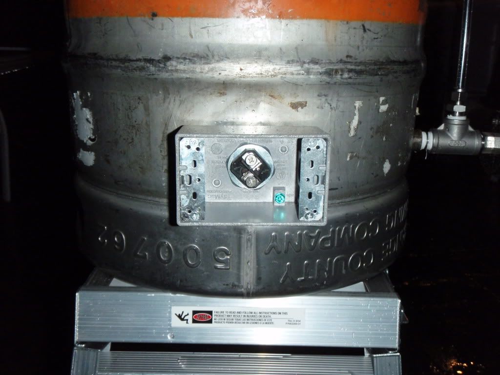
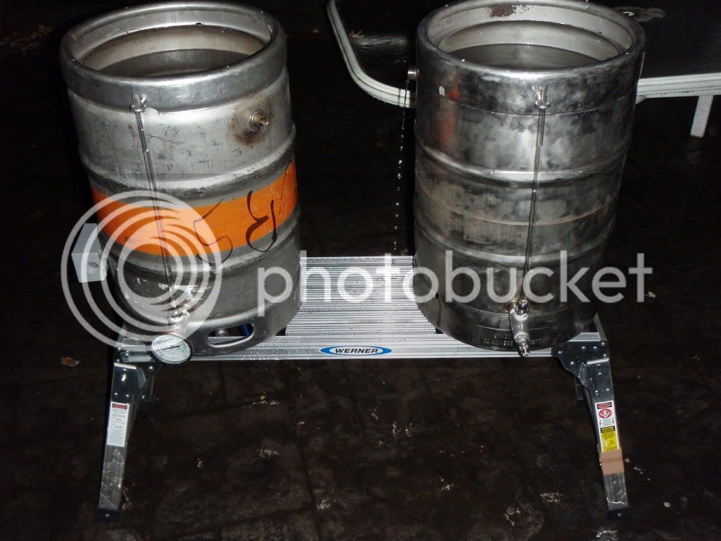
1) I wanted to weld the dump on to the bottom of the kettle, then weld legs to the skirt. Is there any reason not to weld the legs on? For safety's sake I would rather go this route than have the thing on a stand.
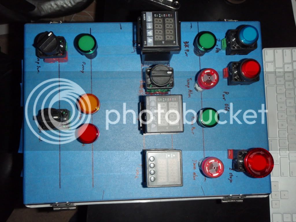
2) I plan on running a 1 1/2" rims tube and would like to be capable of doing 10 gal batches with this setup, although I'm starting at 5 gal batches (limited by the no-sparge an 10 gal round cooler). What size element would be a good fit? I'm going to be on a 30A 240 4 wire circuit. The plan for the BK is a 5500W ULD. As far as RIMS I'd like to be able to step/ramp mash effectively on 5 gal, so I guess I can go up to 5500W, but that seems way overkill.
3) If instead of a 10 gal round cooler I go with a second keg (legs and bottom dump like the BK) and insulate it, will a RIMS keep up with temps efficiently or will I be constantly heating it? I'm seriously considering this route, but I really don't want to be burning a truck load of coal every time I do a beer.
1) I wanted to weld the dump on to the bottom of the kettle, then weld legs to the skirt. Is there any reason not to weld the legs on? For safety's sake I would rather go this route than have the thing on a stand.
2) I plan on running a 1 1/2" rims tube and would like to be capable of doing 10 gal batches with this setup, although I'm starting at 5 gal batches (limited by the no-sparge an 10 gal round cooler). What size element would be a good fit? I'm going to be on a 30A 240 4 wire circuit. The plan for the BK is a 5500W ULD. As far as RIMS I'd like to be able to step/ramp mash effectively on 5 gal, so I guess I can go up to 5500W, but that seems way overkill.
3) If instead of a 10 gal round cooler I go with a second keg (legs and bottom dump like the BK) and insulate it, will a RIMS keep up with temps efficiently or will I be constantly heating it? I'm seriously considering this route, but I really don't want to be burning a truck load of coal every time I do a beer.

")


 Quaffer - thanks for that awesome writeup on soldering the 1" nut to a keg. I'm going to use that thread a LOT when it comes time to build out my kegs. I'm a whole lot more confident in my ability to solder than I am in my or anyone I know's welding skills.