Its finally here!! (Yes, yet another build thread...)

Homebrew Talk - Beer, Wine, Mead, & Cider Brewing Discussion Forum

Help Support Homebrew Talk - Beer, Wine, Mead, & Cider Brewing Discussion Forum:

This site may earn a commission from merchant affiliate links, including eBay, Amazon, and others.

flatulentfox

Well-Known Member
Joined
Jan 23, 2011
Messages
107
Reaction score
5
Location
nashville
I've been planning and thinking for about six months now. I finally have all the parts for the control panel and am almost ready to start wiring. I am currently painting the sheet metal panel and will hopefully have it wired by the end of next week.

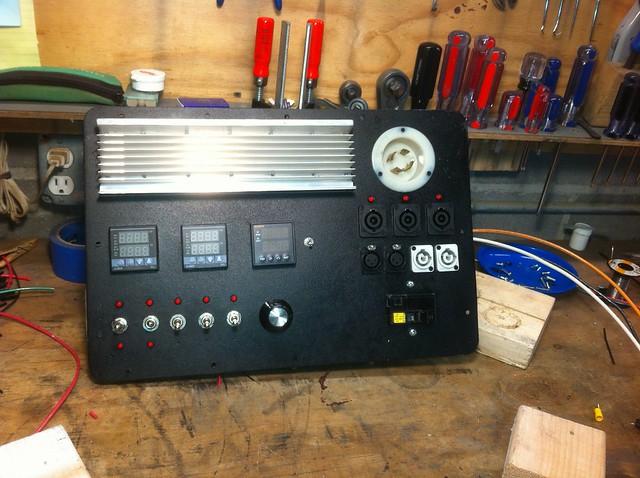
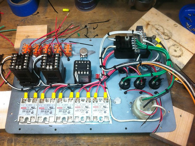
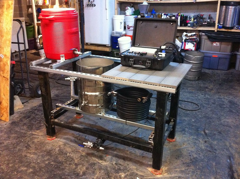
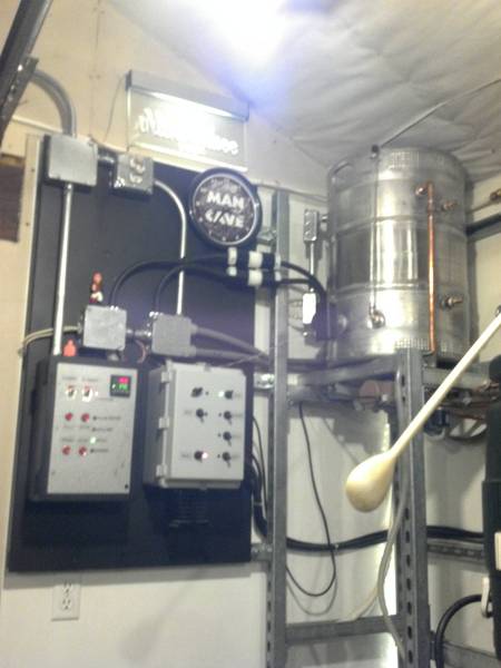
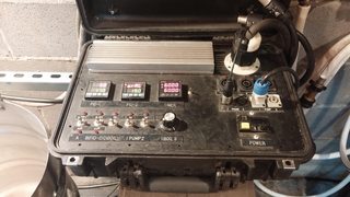
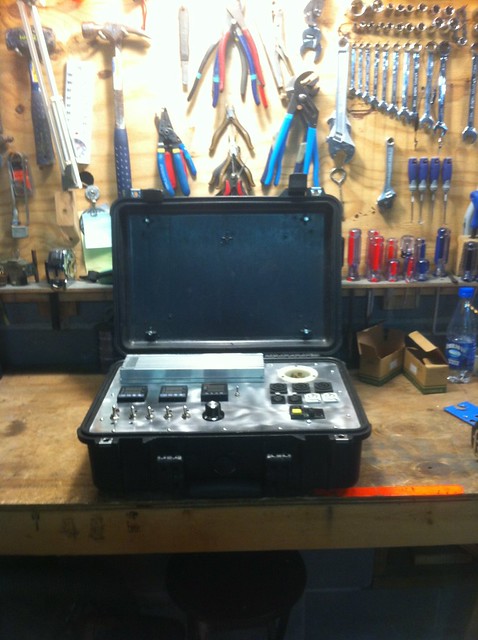
There will be two PIDs and one PWM circuit. The first output (SSR #1) will be switchable to be controlled by PID #1 or by the PWM circuit. The second output (SSR #2) will be controlled by PID #2 and be switchable between 120V and 240V. The third output (SSR #3) will always be controlled by the PWM circuit. There will be two outputs (switched 25A SSRs) for pumps. This gives me the capability to control a full three vessel single tier rig or something as simple as a BIAB system. I plan on using it now as a two vessel two tier Brutus 20 type system. Here are a few pics.

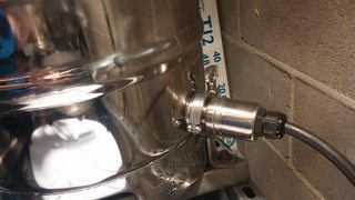
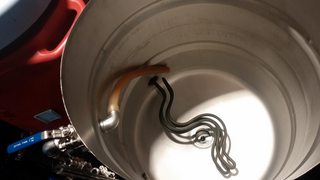
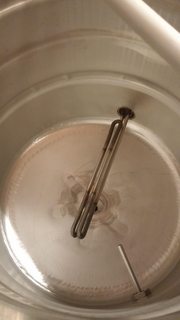
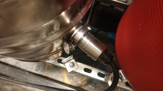
More to come. I have my kegs and have cut them open and started polishing them...

6854820939_5d78323ba6.jpg


6854820351_1503af3ffc_z.jpg


6854820525_45e4d26b86_z.jpg


6854820711_199cc03e9e_z.jpg
 
How do I rotate the pics in my post? They show up correctly if I open them on my computer, but cant seem to rotate them here???

[edit]

got it
 
It looks like there will be a lot of wires in not a whole lot of space...

Take your time, use the zip ties and those sticky squares and good luck!
 
Got the panel painted and got most of the high voltage wiring done tonight.

6867388813_d5f1f22efe_z.jpg


I used this to paint it. Im not super impressed yet, time will tell...

6867388379_b89a689047_z.jpg
 
Wiring question:

I have a 12VDC power supply that will be used for various control purposes and for powering my indicator LEDs. The Auber PIDs have a SSR output for connectiogn directly to the relevant SSRs. Can the negative SSR output of the PIDs be tied to my 0VDC bus, and the positive SSR output be routed around the same as the rest of my +12VC bus? This matters because I have one SSR that will be switchable to be controlled either by a PID or by a separate PWM circuit. Ideally, all the negative terminals (which on the Auber PWM I assume is 0VDC relative to ground) will share a common bus and all the +12VDC will share a common bus. Does this make sense? I am sure my terminology is not all correct.. Any help here would be appreciated!

I know I can meter all this, but I have not powered the system as a whole yet, and would like to avoid powering it yet if I can...

Thanks!
 
It's alive! I still need to clean up the wiring a bit. I had a few design changes while working on it, so it's not as pretty as I could be... But at least everything seems to be working as it should!

More to come.

image-1136860916.jpg
 
That's pretty cool! I like when we (homebrewers) think "outside" the box and create some cool stuff. Keep the pics coming.
 
So, I never drew up a schematic. I just sort of had it all planned out in my head. I had a few design changes as it was was being put together, and as a result, its not quite as pretty as it could be. It should get the job done though. I need to get my BK plumbed, and then I can actually take it for its first test run! That is probably a few weeks away still.

6904136365_04e8015c0d_z.jpg


I had to cut out some of the plywood back panel I had installed as I had not accounted for the depth of the 2532s. Those things are deep...

I have originally planned on mounting bus bars on the wood inside as well and running every component back to the appropriate bus, But decided this would lead to too large of a bundle of cable going between the panel and the case. Instead I jumped everything together on the panel itself and mounted some small bus bars on the PVC piece being that is holding the breaker in place. Its a lot of wire crammed in there, but better than a huge stiff bundle that has to be folded every time the panel is removed.

6904137685_1beac5dfc5_z.jpg
 
I've slowly been making a little progress. Here are a few pics.

I built my couter flow chiller, finised plumbing for my HLT/BK, and got started on the stand

I'll post more details if anyone is interested.

More to come.

image-2546210223.jpg


image-156699823.jpg


image-3116422174.jpg


image-944456835.jpg


image-1902428170.jpg
 
What kind of tri-clamp fits to the sanke fitting? I don't know that I've seen this done before! I also really dig the control box. Reminds me of the digital trainer we got in school.
 
mightyscoop said:
what kind of tri-clamp fits to the sanke fitting? I don't know that i've seen this done before! I also really dig the control box. Reminds me of the digital trainer we got in school.

2"
 
I think I am finally for my first eBrew this weekend!!

My RTDs should be here tomorrow. I then have everything I need to brew. There are still several details to touch up. Pump and CFC mounting will probably be revisited. I will be putting in a false bottom style hop filter as I prefer just throwing in the hops, but will probably use a hop spider for the next few brews.

The brew stand is an old work bench frame I have had for a while. I bolted some unistrut to it and now I have a brew stand. I used composite decking as the table/work surface.

The cooler mash tun will (hopefully soon) become a keggle with false bottom and RIMS. For now I am going to experiment with recirculating though the PID controlled boil kettle to maintain temps.

7066026971_d708bdd334_c.jpg
 
Nice build! I've always been a fan of strut for projects. You may want to consider inverting your CFC so the connections are on the bottom for complete drainage.
 
Nice build! I've always been a fan of strut for projects. You may want to consider inverting your CFC so the connections are on the bottom for complete drainage.

Thanks, I hadn't thought about that at all. I'll do that. I haven't used it yet (other than a pressure test).
 
Oh lordy. A nuclear football for a controller board. If the Feds ever raid your place, you're going to have a lot of explaining to do.
 
LandoLincoln said:
Oh lordy. A nuclear football for a controller board. If the Feds ever raid your place, you're going to have a lot of explaining to do.

Hopefully they will never have a reason to!
 
I made some upgrades. I finally added a HLT. I brewed my first batch last weekend. My efficiency was extremely low. I think perhaps i sparged to quickly. I still have a few things to work out i suppose. Hopefully I will be adding a rims tube and keggle MLT soon...


I also got a stainless chugger pump head. It pumps noticeably faster than the plastic March head I had. The inlet port is a larger bore and the fins on the impeller are larger than those of the March.
 
Is that your gfci mounted to the panel? I have been thinking about doing the same. Any suggestions?
 
Man I love the toolbox/case control panels so much. I've never once moved my brew rigs but for some reason the mobile panels are just sweet!
 
Is that your gfci mounted to the panel? I have been thinking about doing the same. Any suggestions?

You can see how it is mounted in the pictures on the first page. I used a piece of plastic i had laying around and tapped some holes and used screws to sandwich the breaker in place, screws being tightened from the front of the panel.

The breaker is a commercial bolt on type, not the typical "stab on" type you will find in most residential electrical equipment. I used the bolt on tabs as mounts for ring terminals.

I bought the breaker on ebay, as bolt on gfci breakers can be pretty pricy...
 
Yeah, i have never needed to travel with my brew panel, but its nice being able to close it up and put it out of the way some where for cleaning up, moving things around, etc.
 
Back
Top