ebay aquarium temp controller build

Homebrew Talk - Beer, Wine, Mead, & Cider Brewing Discussion Forum

Help Support Homebrew Talk - Beer, Wine, Mead, & Cider Brewing Discussion Forum:

This site may earn a commission from merchant affiliate links, including eBay, Amazon, and others.
Hi

If you believe that the compressor on a normal cheap / small freezer only cycles once or twice a day that's fine. My observation of brand new freezers does not match yours. For a very large freezer or a cold environment anything is possible. The published data from the manufacturer also does not back up the few cycles a day observation.

Bob

Seriously, are we still on this? First, I said "a few times a day", not once or twice. Second, the manufacturer data is for running the freezer at below freezing temperatures, with much less thermal mass inside of them, and with a completely different probe set-up than what I use, so it doesn't have any relation to what we're discussing. I don't just believe it cycles a few times a day, I know it. It's located right next to my desk in my home office, and on days when I work from home I can clearly hear it every time it turns on or off. The reason your observations don't match mine is because you haven't tried or observed the methods of temperature control that myself and many others have suggested.

Like I said earlier, simply raising the freezer temp from below freezing to beer serving temps should decrease the cycling significantly, reducing it to a fraction of what it was. If your system is cycling as often as the manufacturer specs at serving temps (as you suggested earlier), you really should re-think the way you have it set up. If you read the troubleshooting section of any freezer manual you'll see that the solutions for the freezer cycling too often or running continuously are to turn the thermostat up, and/or add thermal mass to the inside of the freezer. That alone should tell you that running the freezer at a significantly warmer temp and packed with a large thermal mass should reduce cycling to below the specs.

Since you seem so familiar with tech specs for chest freezers, you should be well aware that they are designed to run 80-90% of the time when in stock configuration and in normal use to store frozen foods. They are designed this way to reduce energy use, since so much energy is required at compressor start up. Take a look at the numerous stories of people who have converted chest freezers into super efficient refrigerators by adding an external thermostat set at ~36°-40°F (sound familiar?). Many of these people use kill-a-watt meters to record the energy usage, and they show that the freezer only runs once every couple of hours, and averages ~90 seconds of run time out of every hour, which is only 2.5% of the time. With this in mind, is it really so hard to believe that with kegs full of beer which have a larger thermal mass than a fridge of assorted food, and the probe secured to something with some thermal mass, my freezer would run for much longer than 90 seconds at a time, but only a few times a day?

As I said before, your method will work fine, but it will also cycle more than necessary, and require a bit of guesswork/trial and error to get the temperature and hysteresis set correctly. I'm not sure why you continue to argue with these facts, but I'm done repeating myself.
 
Interesting. I wasn't aware that any manufacturers were publishing data on compressor cycling when using an auxiliary temperature controller with the sensor placed on an almost ideal 20Kg thermal mass, in a freezer that likely has several other similar vessels acting as, to use a fancy term like you are fond of doing, defluctuators.

You really should wait until you actually own the controller discussed in this thread, not the 220V you ordered after all of your equally deep analysis of the seller had you convinced it would be a 110V model.

You do not have this thought out properly, and seem to be very closed minded to any methods that differ from your own. There are people here that are equally (or more) intelligent, educated, experienced, knowledgeable, etc. as you. You might try considering the opinions offered up here, even though they might conflict with your ill conceived ideas.

Hi

Oddly enough I have quite a few of these controllers, and indeed the 220V unit does run on 110V.

As to the rest of your bs, it's hardly worth responding to.

Bob
 
Oddly enough I have quite a few of these controllers, and indeed the 220V unit does run on 110V.
Unless something has changed, the 220V will power up on 110V, but does not have enough power to activate the relays.

As to the rest of your bs, it's hardly worth responding to.
This is what we have been hoping for from you for some time.

None of your input to this thread has been of any use to anyone, and indeed has been detrimental.
 
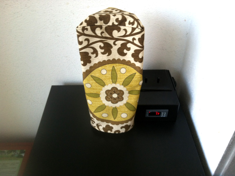
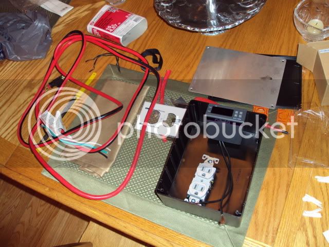
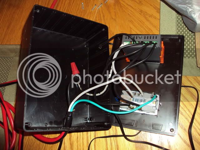
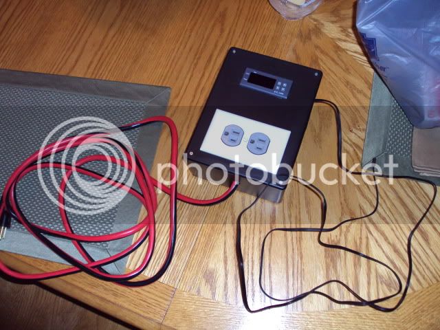
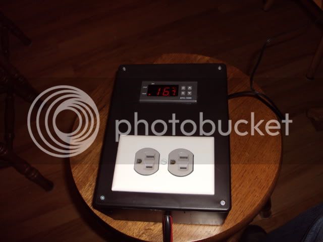
Here are a couple pics of my finished controller. I wanted it to be smaller in size and I managed to fit it in a 6x4x2" project box.
temp-controller---front-55299.jpg

temp-controller---back-55300.jpg
 
Well, the first temperature controller got lost in the mail, so I went ahead and bought one from Mixtea - he's $4 more than some of the other sellers, but at least I know I should get the right version and in a reasonable timeframe. I've already got everything else except the project box, so I'm excited to build mine up in a couple weeks. :)
 
Unless something has changed, the 220V will power up on 110V, but does not have enough power to activate the solenoids.

.

Hi

You really don't know anything about these controllers at all do you?

There aren't any solenoids in them. The relays that *are* in them do indeed function at 110V on a 220V unit.

Bob
 
Seriously, are we still on this? First, I said "a few times a day", not once or twice. Second, the manufacturer data is for running the freezer at below freezing temperatures, with much less thermal mass inside of them, and with a completely different probe set-up than what I use, so it doesn't have any relation to what we're discussing. I don't just believe it cycles a few times a day, I know it. It's located right next to my desk in my home office, and on days when I work from home I can clearly hear it every time it turns on or off. The reason your observations don't match mine is because you haven't tried or observed the methods of temperature control that myself and many others have suggested.

Like I said earlier, simply raising the freezer temp from below freezing to beer serving temps should decrease the cycling significantly, reducing it to a fraction of what it was. If your system is cycling as often as the manufacturer specs at serving temps (as you suggested earlier), you really should re-think the way you have it set up. If you read the troubleshooting section of any freezer manual you'll see that the solutions for the freezer cycling too often or running continuously are to turn the thermostat up, and/or add thermal mass to the inside of the freezer. That alone should tell you that running the freezer at a significantly warmer temp and packed with a large thermal mass should reduce cycling to below the specs.

Since you seem so familiar with tech specs for chest freezers, you should be well aware that they are designed to run 80-90% of the time when in stock configuration and in normal use to store frozen foods. They are designed this way to reduce energy use, since so much energy is required at compressor start up. Take a look at the numerous stories of people who have converted chest freezers into super efficient refrigerators by adding an external thermostat set at ~36°-40°F (sound familiar?). Many of these people use kill-a-watt meters to record the energy usage, and they show that the freezer only runs once every couple of hours, and averages ~90 seconds of run time out of every hour, which is only 2.5% of the time. With this in mind, is it really so hard to believe that with kegs full of beer which have a larger thermal mass than a fridge of assorted food, and the probe secured to something with some thermal mass, my freezer would run for much longer than 90 seconds at a time, but only a few times a day?

As I said before, your method will work fine, but it will also cycle more than necessary, and require a bit of guesswork/trial and error to get the temperature and hysteresis set correctly. I'm not sure why you continue to argue with these facts, but I'm done repeating myself.

Hi

If you take a brand new un-modified freezer and load it up in a normal fashion with turkeys and pizza, the compressor cycles in the manner they designed it to cycle. That cycle rate is not something that is going to destroy the compressor.

With me so far?

Bob
 

Would you mind including a few more pictures of how you wired up the mini-jack? I'm assuming you cut off the probe and wired it to the jack (inside the box), and then wired the probe to the jack for easy connectivity? Did you notice any resistance change when doing so?
 
Would you mind including a few more pictures of how you wired up the mini-jack? I'm assuming you cut off the probe and wired it to the jack (inside the box), and then wired the probe to the jack for easy connectivity? Did you notice any resistance change when doing so?

I'm interested in this as well! Isn't the temperature probe a cheap RTD? I would think any change in resistance could screw up the reading.

That's a really nice clean build though :mug:
 
I'm interested in this as well! Isn't the temperature probe a cheap RTD? I would think any change in resistance could screw up the reading.

Interesting. I did exactly the same thing (soldered in an 1/8" phono jack so I could disconnect the probe). I'll check and see how accurate the temperature readings are when I get home...
 
Hi

You really don't know anything about these controllers at all do you?

There aren't any solenoids in them. The relays that *are* in them do indeed function at 110V on a 220V unit.

Bob
You got me there, a catastrophic late night word choice error of solenoid instead of relay (fixed now). Functionally, they both use the same principle, and the reason either won't work when under powered is the same- insufficient current.

What is your excuse for *still* trying to make a case for putting the sensor directly on the evaporator coils of the freezer?

Like I wrote previously, and which you again failed to read thoroughly, the previous 220V models indeed do not work on 110V. Until there are more reports of other hapless people mis-ordering the 220V unit, and verifying that the newer models also works on 110v, it is wise to buy from one of the sellers that explicitly states it is for 110V.

You have already cluttered up this thread with misinformation about sensor placement, please don't add to the confusion by saying the 220V units work on 110V, at least until it is proven that newer units have had some kind of component change allowing 220/110V.
 
None of your input to this thread has been of any use to anyone, and indeed has been detrimental.

I think that's a bit harsh and uncalled for. Just drop it each of you....... There's a place for this flaming. Do it there. :drunk:

Except for that it's true. First he advocated putting the sensor directly on the evaporator coils, and even defended it (and still is) when it was questioned . Now he is adding more confusion by stating that 220V units will work on 110V. While this may be true if newer 220V models use a different transformer or relays, there is insufficient evidence to state that 220V units work on 110V, especially in a blanket statement like his previous post, when it is a known fact that previous 220V units as recent as 1 month ago do not function on 110V.
 
RTDs shouldn't have much of a problem with the phono plug. Thermocouples are where you mostly always run into problems with adding extra connections.
 
RTDs shouldn't have much of a problem with the phono plug. Thermocouples are where you mostly always run into problems with adding extra connections.

Well, with thermocouples as long as you keep the same metals so there are no other junctions it's good to go, but this is a cheapo 2-wire RTD. It's not a 3 or 4 wire RTD, so the resistance in the wires doesn't cancel, it's added to the resistance of the sensor. So you need to keep it as small as possible. I think the sensitivities of these things are pretty impressive (.004 ohms / deg C? something like that) so adding in even a tenth of an ohm would give you a significant error. I guess that would mostly be an offset though, so you could correct for that in the controller setup.
 
Hi

If you take a brand new un-modified freezer and load it up in a normal fashion with turkeys and pizza, the compressor cycles in the manner they designed it to cycle. That cycle rate is not something that is going to destroy the compressor.

With me so far?

Bob

If you take a brand new unmodified freezer that happens to have been designed with a crappy ASD implementation, plug it in for 20 seconds, unplug it for 10 seconds, then plug it back in, your compressor motor has a good chance of burning up in < 1 hour. Does that mean it behaved in the manner they designed it to function?

Also, cycling frequency is precisely what (eventually) destroys the compressor/motor. For a typical compressor/motor, cycling frequency is a much greater factor for longevity than total run time, although for the same system, increased cycling frequency usually correlates to increased total run time as well. So, increased cycling frequency is doubly bad.

Running the compressor for fewer longer periods, rather than many short ones is exactly why the temp differential on factory thermostats is so large (~5F). Most factory probes are usually just hidden behind a plastic shroud, and rely on the slow response of the bulb style probe as part of the control system.

The STC-1000 probes are extremely fast responding, and require a different approach. The strategy favored here is to place the probe on something thermally massive (topped by insulation), which allows the cycling frequency to be easily controlled by simply adjusting the temperature differential.
 
Would you mind including a few more pictures of how you wired up the mini-jack? I'm assuming you cut off the probe and wired it to the jack (inside the box), and then wired the probe to the jack for easy connectivity? Did you notice any resistance change when doing so?

Well without taking apart the box since it was tight fit in the small box I will explain what I did. All the parts were from Radio Shack. The mono headphone jack (female) was mounted to back wall of the project box. Only needed to drill a hole. I then soldered wires to the back of the jack (inside the project box) and ran the wires to the probe input on the STC-1000 controller.

The probe I received with the STC-1000 had bare wires on the end. I just soldered them to the mono headphone plug (male).

As for any problems...not that I noticed. Plugged it in and checked the temp in an ice slurry and it was +.3 degree Celsius off from reading 0.

The only reason I went with the plug was for easier replacement if needed and if I want to run two different probes. I could have a separate probes on two vessels and swap the plug to monitor on the one I choose.

Hope that all makes sense. Any other questions let me know.
 
Well, with thermocouples as long as you keep the same metals so there are no other junctions it's good to go, but this is a cheapo 2-wire RTD. It's not a 3 or 4 wire RTD, so the resistance in the wires doesn't cancel, it's added to the resistance of the sensor. So you need to keep it as small as possible. I think the sensitivities of these things are pretty impressive (.004 ohms / deg C? something like that) so adding in even a tenth of an ohm would give you a significant error. I guess that would mostly be an offset though, so you could correct for that in the controller setup.
There have been a few discussions in this thread about using the phono jacks. From memory, no one noticed any difference in temps, or had to account for any offsets due to the extra resistance of the jack/connections. Like you guys, I was a bit surprised as well.

I remember seeing a graph for what was supposed to be a similar probe (to use as spares), but don't recall the exact Ohm/C relationship. Is it really 0.004 Ohms/C in the normal usage range? I thought is was ~1 Ohms/C, and that is why the guys didn't experience any effects from the extra connections.

Either way, the unit has a calibration setting, so it is an easy fix if needed.
 
Hi

If you take a brand new un-modified freezer and load it up in a normal fashion with turkeys and pizza, the compressor cycles in the manner they designed it to cycle. That cycle rate is not something that is going to destroy the compressor.

With me so far?

Bob

I never said otherwise, but why on earth would you choose to use a probe placement that results in that type of cycling at beer serving temps when you could so easily significantly reduce power use and extend the life of your freezer? Even simply increasing to serving temp by changing the t-stat coarse adjustment screw, as many people in this thread have done, will reduce the cycling to a small fraction of what you're experiencing. Besides that, you've already unwittingly admitted in this thread that your probe placement results in cycling that's worse/more frequent than the stock configuration at freezing temps, even though you're at serving temps. See below-

Hi

Very true except for *right now*. I just finished cleaning all my beer lines. When I do that I unplug the keezer. Just got it back on power and now I have to wait an extra 10 minutes to start cooling down..... I'm THIRSTY ....

Bob

Hi

But my liver's thirst too....

Also looks like the short cycle prevention is doing it's thing just fine. Held off for 10 minutes after power up. Then cooled down and cut out. Since the beast is warm inside, it went back up pretty fast. Short cycle cut in and it holding off re-starting the compressor.

Still thirsty ...

Bob

The ASD shouldn't have to kick in when you add ferm temp kegs or unplug the freezer for a little while to clean the lines. Most freezers don't have an ASD built in, but the bulb type sensor and shielded placement all serve to prevent short cycling even without it. Good thing you had and were using the ASD function, otherwise you might have damaged your compressor with your probe placement. Further proof that while it might work, it's less than ideal.

I'm interested in this as well! Isn't the temperature probe a cheap RTD? I would think any change in resistance could screw up the reading.

That's a really nice clean build though :mug:

I added phono jacks to the single stage controllers similar to the STC-1000 that I use in my HERMS, and only had to adjust the temp calibration by 1°F. I then added another connection and doubled the wire length, which required me to adjust them by another 2°F, for a total change of 3°F.
 
There have been a few discussions in this thread about using the phono jacks. From memory, no one noticed any difference in temps, or had to account for any offsets due to the extra resistance of the jack/connections. Like you guys, I was a bit surprised as well.

I remember seeing a graph for what was supposed to be a similar probe (to use as spares), but don't recall the exact Ohm/C relationship. Is it really 0.004 Ohms/C in the normal usage range? I thought is was ~1 Ohms/C, and that is why the guys didn't experience any effects from the extra connections.

Either way, the unit has a calibration setting, so it is an easy fix if needed.

Ah, you're right. I was remembering wrong. It's a factor of .004 per degree C, not .004 ohms. So that's 0.4 percent change in resistance per degree C. If it's a 100 ohm RTD, that means you're looking at 0.4 ohms per degree. I'm guessing one of those jacks would add maybe half an ohm at the most, probably a lot less.

Sorry I didn't see the discussion above!

From JuanMoore's response I guess this is confirmed. It adds a tiny offset but not a big deal.
 
I added phono jacks to the single stage controllers similar to the STC-1000 that I use in my HERMS, and only had to adjust the temp calibration by 1°F. I then added another connection and doubled the wire length, which required me to adjust them by another 2°F, for a total change of 3°F.

Mind posting the make and model number for your single-stage? I'm curious if it's the same unit I have.

Thanks.
 
Mind posting the make and model number for your single-stage? I'm curious if it's the same unit I have.

Thanks.

No model # that I'm aware of, but they're made by Wilhi, just like most of the STC-1000's appear to be. They're only single stage, and display in fahrenheit. Look like this-

http://www.ebay.com/itm/Digital-Temperature-Controller-Thermostat-Aquarium-120V-/261032736341?_trksid=m7&_trkparms=algo%3DLVI%26itu%3DUCI%26otn%3D3%26po%3DLVI%26ps%3D63%26clkid%3D167592514276601139&_qi=RTM1084481#ht_3696wt_1396

Interesting... Mine looks like this:
Controller_Face.JPG


but displays in C and has a model # (WH7016C):
Controller_Top.JPG


Does yours have the same wiring as mine? Just curious. Thanks!
 
has anyone measured the resistance of the temperature probe, or figured out what type it is? I would like to try one of these controllers but I want to make a waterproof/food grade temp probe.
 
barrooze said:
Does yours have the same wiring as mine? Just curious. Thanks!

Yep, looks like the same wiring.

BetterSense said:
has anyone measured the resistance of the temperature probe, or figured out what type it is? I would like to try one of these controllers but I want to make a waterproof/food grade temp probe.

The specs for the probe are listed in the manual that comes with it, and can also be found online. I'm on my phone, but I'm sure someone can post specs for you. FWIW the probe that comes with the single stage units is SS, unlike the oval rubber blob that comes with the STC-1000.
 
barrooze said:
Interesting... Mine looks like this:

but displays in C and has a model # (WH7016C):

Does yours have the same wiring as mine? Just curious. Thanks!

I have the same WILLHI controller that I am trying to wire up to a single receptacle, having one outlet for the keezer and the other outlet for a lamp
 
BetterSense said:
has anyone measured the resistance of the temperature probe, or figured out what type it is? I would like to try one of these controllers but I want to make a waterproof/food grade temp probe.

I bought a few SS probes last year for my STC-1000s, as I wasn't a fan of the rubber probe. I believe this is the exact one, which is even threaded: http://www.ebay.com/itm/Air-Water-T...ultDomain_0&hash=item19d23d5e1d#ht_1628wt_689

What you want are 10K ohm NTC sensors (NTC = Negative Temperature Coefficient).
 
I got my WILLHI temp controller wired in tonight, the outlet is not 1/2 always hot and 1/2 controlled by controller, but that's ok. The temp is set at 3° C right now, so I'll monitor it overnight to see how it does. A BIG THANK YOU goes out to everyone here on the boards for the advice and wiring help.
 
After procrastinating for a few weeks after getting my STC-1000 in the mail, I finally wired up my control box last night (which I'd previously built but not wired). I had some special requirements, as I wanted a box that would not only control my kegerator, but also offer two switched plugs (not full outlets, just individual receptacles), one for the tower fan in my fridge and the other for our balcony lights, as that's where the whole setup is.

The end setup consists of a RadioShack project box (the biggest one they had, not sure of the precise dimensions), two electrical outlets (for a total of four receptacles), and two standard light switches, along with the STC-1000. The two switches independently control both receptacles on the left side of the box, one for the fan and one for the lights, and the right side receptacles are controlled by the STC-1000 (one hot, one cold, though I'm only using the latter for now). I had inspiration from someone else earlier in this thread who also used a RadioShack project box and mounted their outlets on the side, which let me know that there'd be enough vertical clearance for the outlets and the faceplate.

Here are a few shots of the end product, though I'll note that those two white plugs coming off the side are going to be replaced with some rotating low-profile extension cords that will look a lot nicer (and match the box to boot). Very happy with the way this came out! You can also see the tap sleeve cover that my fiancé made for the tower (it's outside so I wanted to protect it while not in use).

two.jpg


three.jpg


one.jpg
 
I am, and the box will also be moving in a month or two once the last part of the kegerator balcony project is completed. We'll be building a table surface that will sit on top of the kegerator, and expand across to the opposite corner of the nook it's sitting in. At that point, the control box will sit a few feet away from the taps.
 
i was excited about the prospect of this temp controller, so i got one from ebay and put the whole thing in a project box from radio shack. one plug is switched for heating and the other for cooling. i have yet to build up my fermentation chamber that i'll use this on, but preliminary tests confirmed that the unit worked great. there is a 0.3 deg C differential on this thing, so it is pretty accurate and easy to set. i used a 14 gauge extension cord for all the wires. it does read in celcius, but that's OK by me.

all of the parts:
DSC00889.jpg


did some sloppy cut outs and wired it up:
DSC00899.jpg


power cord and sensor gives plenty of slack:
DSC00892.jpg


close up of the temp controller:
DSC00896.jpg


powered up:
DSC00890.jpg


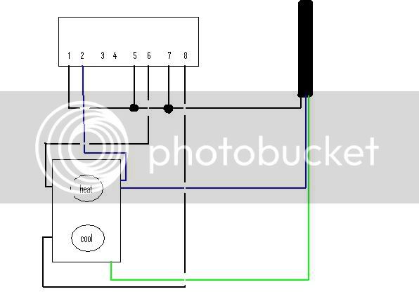
my wiring diagram (sloppy also). i only used one wire nut to join the hot wires as you can see in one of the pics above. also, very important to break off the jumper tab on the hot side so you can control each outlet independently.
possibleschematic.jpg

I want to use both receptacles of the electrical socket when the cool side of the controller is engaged - this is so I can run the keezer and a 110v fan internally at the same time.

Do I leave the tab between the two contacts intact for this to work?
 
I want to use both receptacles of the electrical socket when the cool side of the controller is engaged - this is so I can run the keezer and a 110v fan internally at the same time.

Do I leave the tab between the two contacts intact for this to work?

Yes and you wouldn't wire the hot (from terminal #6) for heat to the outlet as the diagram has. You'd wire that to whatever your heat source outlet is (another outlet)
 
Back
Top