ChuckJaxFL's PWM

Homebrew Talk - Beer, Wine, Mead, & Cider Brewing Discussion Forum

Help Support Homebrew Talk - Beer, Wine, Mead, & Cider Brewing Discussion Forum:

This site may earn a commission from merchant affiliate links, including eBay, Amazon, and others.

chuckjaxfl

Well-Known Member
Joined
Feb 16, 2010
Messages
331
Reaction score
23
Location
Jacksonville, FL
I finally put together a PWM.

A friend wanted a PWM to use alongside the PID already installed in his awesome BIAB system. He's more than capable of building his own, but I told him I wanted to throw one together for him.

He didn't want a DPDT between the PID & the PWM. I forget now why, but that was one of the design goals. We started, initially, to consider just putting diodes on the +'s of both the PWM and PID. Once the PWM was turned on, the temp would rise and the PID would stop sending signals. I wanted a tighter control, so this is what I came up with.

 
Last edited by a moderator:
Some pics

image-4055375811.jpg


image-192077746.jpg
 
The PWM can run on 7-12vdc. The PID is wired into the PWM, rather than the SSR. When the switch is in the "off" position, the PID controls the SSR. Once turned "on", the PWM takes over control of the signal.

The schematic & board were drawn in Cadsoft Eagle (freeware version). I used iTead's CAM files to create the gerber files for the boards, and then had them produce the boards for me. I emailed the files on 7/8/12, the boards arrived 7/30/12. 10 boards cost me $18.90 to the door. It would have been less, but I got them in black, just because.

I considered using a 555, but went with an ATtiny85 instead. With a 555, I'd have to recalculate resistors and capacitor values, and then actually break out a soldering iron again to change anything. With this chip, I can change the code on it in seconds if I want to change the function. The downside is the ATtiny85 costs a little more and requires a voltage regulator.

It was going to be all through-hole parts, but CS223 encouraged me to try using these surface mount components. The parts on the back (that 8 pin chip, the two brick shapes pieces and the voltage regulator) were a breeze. Much easier than expected. On the front, there's 8 or 9 components in that little area behind the potentiometer. They are 0603 components (0.06" x 0.03"). This is the LAST time I'll use them. WOW those are tough to handle. The take-home lesson is to stick with the surface mount stuff (small & cheap), but use the more manageable 0805 or 1206 parts. I've got enough parts to make a handful of these PWM's. Maybe once I'm done, I'll have had enough practice to think differently.

If there's some way to do it, I'll zip the Eagle files and post them here. I put the OSHW logo on there, and the CC-SA license in hopes that someone will take the files and build something more impressive.

The code is stupidly simple:

Code:
#define potPin 1
#define ssrPin 4
#define windowTime 1000
unsigned long markTime=millis();

void setup(){
  pinMode (potPin,INPUT);
  pinMode (ssrPin,OUTPUT);
}
void loop(){
  int period = map(analogRead(potPin),0,1023,0,windowTime);
  if ((millis()-markTime)<period) digitalWrite(ssrPin,HIGH);
  if ((millis()-markTime)>period) digitalWrite(ssrPin,LOW);
  if ((millis()-markTime)>windowTime) markTime=millis();
}


The code could easily be modified, though. For instance, you could have the knob start at 30% instead of 0%. Or max out at 80% if you wanted to. Or reverse direction.

For my own copy, I will have the first 10% of the knob cover from 0-40%, the last 10% cover 80-100%, and then have doubly fine control from 40-80% (the range where I suspect most of us are boiling).
 
I'll barter one instead? Click on my name and do the "donate" thing for a membership for me, and I'll send you one. That way, the board here actually gets the money. Sound fair?

Wait until I get another one put together, though. I've got some family here with health issues. If you do send the money, then I disappear for a week or more before I get it to you... that would bother me a lot.

Pm sent! How do you connect to the chip to adjust the PWM? I like the idea of the fine tuning of the percentages but looking for a full off and then full on @ 0 and 100% respectfully.
 
stamandster said:
Pm sent! How do you connect to the chip to adjust the PWM? I like the idea of the fine tuning of the percentages but looking for a full off and then full on @ 0 and 100% respectfully.

I'll have to do that for you before I send it. I temporarily solder a six pin header into the corner and hook up a programmer as I'm assembling it.

Where would you want the center of your 'fine control' band to be?
 
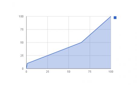
I would also mash with the PWM (at some point get a PID to take that control over, reason for wanting this awesome PWM) ... so maybe more control over those temps. I guess start at 0 knob 0 percent (or off), 1% knob w 10% power to 65% knob w 50% power. Then the rest for boil up to 100% (full on).

Would you be able to keep the header pins in case I wanted to adjust it myself at a later time?
 
stamandster said:
Actually what you have sounds good to me. Would you be able to keep the header pins in case I wanted to adjust it myself at a later time?

Sure. It will look a little weird, as I'll have to use an extended set for the connector to clear the potentiometer housing. It will function fine, though.

I'm going to do a revised version, I think. I want to rotate that header 90° to fix that issue. I also want to shed that mechanical relay. I found a transistor array chip on Digikey that I think will be perfect.
 
I'm assuming it'll work without having to have a PID attached to it? It'll just use it's own logic? (also, I updated my percentages :) I hope thats ok)
 
stamandster said:
I'm assuming it'll work without having to have a PID attached&hellip;

Correct, as long as you have a 7-12vdc power supply. An LED driver from eBay would do, or any wall wort since there's a vreg already on the PWM.
 
stamandster said:
I would also mash with the PWM (at some point get a PID to take that control over, reason for wanting this awesome PWM) ... so maybe more control over those temps. I guess start at 0 knob 0 percent (or off), 1% knob w 10% power to 65% knob w 50% power. Then the rest for boil up to 100% (full on).

Would you be able to keep the header pins in case I wanted to adjust it myself at a later time?

Y'know, you just gave me another idea for the next iteration.

I could add a two position DIP switch, and put four different profiles on chip.
 
I would also mash with the PWM (at some point get a PID to take that control over, reason for wanting this awesome PWM) ... so maybe more control over those temps. I guess start at 0 knob 0 percent (or off), 1% knob w 10% power to 65% knob w 50% power. Then the rest for boil up to 100% (full on).

Would you be able to keep the header pins in case I wanted to adjust it myself at a later time?

So, this is the curve you want? So that 65% of the control covers to 50% output, then ramps up to 100%?

chart_1 (1).jpg
 
So, this is the curve you want? So that 65% of the control covers to 50% output, then ramps up to 100%?

That's great!

I like the idea of a selector :) That way you could have a "mash" profile and a "boil" profile. Although the selector I would think would need to be easily accessible from the front of the panel.

Also, do you have the Eagle files that you were talking about earlier (maybe upload to Google Drive or Dropbox?)? Also, how did you connect it to your pc for programming, serial direct or a usb-serial convertor? Which pins should be connected to what wire? (sorry for all the questions!)
 
I'm looking for an LED driver for this, but, what wattage should I be looking for? I don't want to kill it :)
 
Also, do you have the Eagle files that you were talking about earlier (maybe upload to Google Drive or Dropbox?)?

I can email them to you, PM your email address.

Also, how did you connect it to your pc for programming, serial direct or a usb-serial convertor? Which pins should be connected to what wire? (sorry for all the questions!)

That's a bit beyond the scope of a single thread. To get started, I suggest you pick up an Arduino UNO and download the Arduino IDE, here. ArduinoISP is the sketch you're interested in. It's one of the example sketches that come with the IDE.

Information using the Arduino to program the ATtiny85 is available here.

The pinout is just a standard 2x3 ICSP header, like this on the left:
FR9HXLZGAPV8IA4.LARGE.jpg
.

I'm looking for an LED driver for this, but, what wattage should I be looking for? I don't want to kill it

Well, I bought these, but not for any particular reason. Anything from 7v-12v should do the trick nicely. There's a regulator on board, so almost any old discarded cell charger should do, as long as it's in that range. Wire in a 9v battery if you want.
 
I'm assuming an ATtiny85 could be used to replace the 555 in this stirplate design, correct?

Simple PWM Stirplate Controller

I realize it's probably overkill for something so simple, but I am looking for a fun project to learn about programming microcontrollers, and also need a stirplate, so this might just fit the bill.
 
You mean a direct swap? Chip for chip? No, not at all. You could use the Attiny to read a pot, and set a value to drive a transistor for the fan, though.
Keep in mind, my PWM here or using it to drive a stirplate is a gross underuse of the ATtiny. I've used them so far to run the PID libaray, to read DS18B20's, and to output to an LCD (the LCD has a serial backpack), just not all three at the same time.

If all you want is linear control from 0% to 100%, then using a uc like this is pretty wasteful. I just did these as a "teach myself" project for SMD soldering.
That, and because, for my own PWM, I want 0 to be 0, 100 to be 100, like normal, but I want the majority of the knob to control a narrower band of output and I haven't a clue how to do that with a 555.
 
Here's another I put together w/ no provision for PID included. It's much simpler, just a 555 based PWM.

I put all of the components within a 1.25 circle on the back, w/ the knob & indicator LED's on the front, so anyone could mount it by drilling a 1.25" hole, and 4 small holes.

image-4125871280.jpg

 
Last edited by a moderator:
You're running the arduino libs on the attiny? Can you send me the schematics?

I like this, so simple and nice :)
 
You're running the arduino libs on the attiny? Can you send me the schematics?

The schematic is posted above, the code is posted earlier in this thread.
You can get a lot more done than this with a tiny, though. I've got an ATtiny84 running an LCD, reading a DS18B20, and running the PID library on another board. It uses every pin, and *almost* every byte available. I've been meaning to post it... maybe I can do so tonight.

To get started programming other uC's with Arduino IDE, start here.

I like this, so simple and nice :)

Thanks! I still like it too, and I get private messages from people still requesting them. I think, for use next to a PID, it's hard to beat. For "just a PWM" it's overcomplicated. I also need to go ahead and draw up a 555 version, though. No one but me seems to have a lot of interest in the custom curve aspect made available with the uC.
 
Arise from the dead!

Sorry to revive such an old thread but it's brilliant and I can't believe this isn't used more!

Hey Chuckjaxfl, this is exactly what I'm looking for! PWM used in conjunction with a PID. I've never used the ATtiny but I'm willing to learn. how is your setup wired? I'm thinking of a single vessel build and I want to be able to fine tune a certain range of output so I might be able to better control mash temps but also be able to kick it up for boils. Any thoughts? Thanks dude!
 
Back
Top