My HERMS Build - ready for criticism

Homebrew Talk - Beer, Wine, Mead, & Cider Brewing Discussion Forum

Help Support Homebrew Talk - Beer, Wine, Mead, & Cider Brewing Discussion Forum:

This site may earn a commission from merchant affiliate links, including eBay, Amazon, and others.

Walker

I use secondaries. :p
HBT Supporter
Joined
Sep 8, 2005
Messages
10,982
Reaction score
122
Location
Cary
This has been under development for a while, but I thought I'd throw it out to the dogs and absorb any criticism.

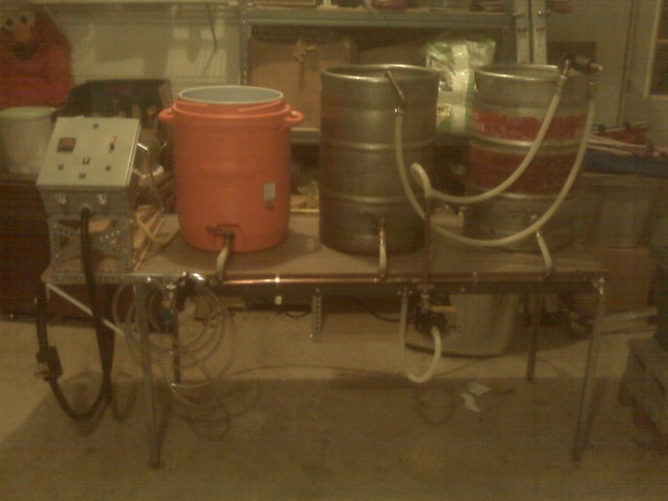
I am going "half way" here to start. One electric vessel.... the BK. It will serve as my HEX during the mash and then the BK later (sparge water will be temporarily moved from BK to a large pot while I pump wort into the kettle after the mash.) This was a cost savings item... the extra power cable, electronics, heater element, ball valve, etc required for a dedicated HEX doesn't seem worth the scorn of SWMBO right now.

I've got ample room in my control box and amps available to upgrade later and add the dedicated HEX.

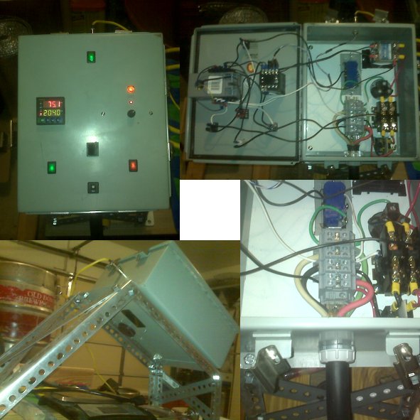
My PID does not have a manual mode, but I built a pulse width modulator for a couple of $'s and will use a selector switch to pick whether the PWM or PID is in control of the heating element. When I eventually add the dedicated HEX, the selector switch will be abandoned and the PID will control the HEX while the PWM controls the BK.

The pic does not show the ground wire, but it'll be there in the system. The control box, pump, and element will be grounded.

So... lend me your criticisms now..... I'm ready for it...

edit: all 120V powered items (except the pump receptacle) are mounted on the hinged door of the control box. The 240V stuff is all in the belly of the beast.

Pandora.jpg


There is one thing I think I could/should have done differently, but I'll just be a nuisance if it happens. In that case, I spend another $10 and fix it and the nuisance goes away. But, I'm not going to point it out to anyone. :D
 
Just curious as to how you are splitting the black hot - the one that goes to the 25a and 15a mini breakers - as it isn't exceedingly clear from your diagram. :)
 
Yeah.... sorry. The diagram does not include the power distribution blocks. I'll add them in and re-post the image later.

but, to answer your question, I have two power distribution set-ups.

One (60A rated) sits in the belly of the box. The main cable wires attach to that and then spread out to other items. Hots out of this distro attach to breakers and nothing else. The neutral out of this distro goes to 120V receptacle, one side of the contactor, and to the door for further distribution. Ground out of this distro goes to the receptacles and the chassis (the box itself is 12 gauge steel, except the door which is 14 gauge.)

On the door of the panel (after the 15A breaker that is fed from the main distribution block), there are smaller 30A rated terminal strips that split the hot and neutral out to the switches, PID, PWM, lamp, etc.
 
Are you using a three-way switch between the PID and the PWM? My only concern would be avoiding a situation where both are on and the system is confused.

Looks Kosher to me.
 
DPDT switch with an "on-on" functionality. It will connect either the 2 PWM relay lines or the 2 PID relay lines to the relay. Not possible to get multiple connections through it.
 
That is a great idea. I would hate to use the manual mode on a PID. PITA!! Using a dial is so much easier during Boil. I often have to adjust my dial during boil. I would be throwing things if I had to adjust with the tiny buttons on the PID.

I would encourage more people to think about this option if they are running two vessel systems. It just seems like the way to go. Great job.
 
Thanks. The PWM idea is not mine, but I might have a slightly different circuit for it than most use. I've seen them wired in a "traditional" way where turning the knob adjusts the duty cycle, but also slightly adjusts the frequency of the thing.

Mine is strictly a duty cycle modulator. The frequency is fixed.

Schematic of the PWM:
PWM1.jpg


I've seen people use multiple PIDs in their systems quite frequently on here. It seemed a waste of $ to control the BK with a PID since that PID would only ever be operated in manual mode. The PWM cost about $3 to build... another $1.50 to package up in a plastic box. Much more cost effective than a PID. The PWM gets its DC power source from the guts of an old cell phone charger I had laying around. I just took the plastic casing off, soldered wires to the place where the plug prongs were making contact and dropped it into the plastic box with the small circuit board that the other items were soldered to.

edit: if I had no plans to upgrade later, a PID with manual mode would be all I needed. No separate PWM. but, since I do plan to upgrade later, I have two separate control devices already (for the same price as a PID with manual mode) and now I don't have to build or buy any more control hardware when that day comes around.
 
Brewmoor...

I just checked your build thread and saw that you are also using a PWM, but you went the extra mile and etched your circuit board! Nice.
 
I am using a similar circuit. I used the schematic from this site.

http://home.highertech.net/~cdp/boilnew/boilnew.htm

It works fantastic. Like you said. It was cheap too. In my case it cost me nothing. I had the parts laying around. I am sure the parts though only would cost a few dollars.

Edit: If anyone is interested in this circuit. I use expressPCB to make my circuit boards. PM me if you want a copy of the file.
 
Yeah... that's the "traditional" wiring I was referring to with the PWM. I'm sure it doesn't make a darn bit of difference to have the frequency change a little when you adjust the duty cycle with the knob, but I have some kooky plans in mind for this thing and I wanted the frequency to be fixed regardless of the knob setting. ;)

Nice work, man. (edit: I like the knob you have.... Mine is kind of small, and I'll probably pop it off and put a different one on at some point.)

Parts for the PWM were cheap cheap cheap from mouser.com, but I did have to splurge on a little IC solder board from Radio Shack ($1) because I simply couldn't find one in the mountain of things that mouser sells and got tired of looking.

For power distribution, I bought modular DIN rail stuff from mouser, too. Considerably cheaper than the big bricks I see often, and I can add more outputs to the distribution block for a few cents as the system evolves.
 
I etched the circuit boards mostly because I was making a few of them. It makes soldering the components on a bit easier. I made some extras for backup and for another rig I am planning to build late spring or summer.

I am going to build a much simpler and much larger system. I will probably look at the modular DIN rails for that project. Dealing with wires and blocks were a pain. Plus this next project won't really be my money being spent;)
 
I etched the circuit boards mostly because I was making a few of them. It makes soldering the components on a bit easier. I made some extras for backup and for another rig I am planning to build late spring or summer.

Well... if you are so inclined, you can probably sell them to folks on HBT. I had posted a schematic and parts list somewhere here before and had a bunch of people ping me asking if I would build and sell them one.

I am going to build a much simpler and much larger system. I will probably look at the modular DIN rails for that project. Dealing with wires and blocks were a pain. Plus this next project won't really be my money being spent;)

The modular DIN rail stuff was a lot cheaper than buying the fixed power distribution blocks, so you'd be saving that person some money by using them.

I bought everything needed to distribute the 4 incoming wires from my primary cable out 3 ways for about $10 total. Adding two more outputs for a wire would cost $0.62, so you can go crazy here if you want and distribute the wires to a lot of places for a low cost.

If you need some DIN rail, let me know. I needed about 6" of it to mount the thing onto, but the shortest length they sold it in was about 5'. The other 4.5' of the stuff is just sitting there.

I thought about mounting my SSR's to it because the heatsinks are shaped so that they will also slide on to the rail, but I opted for just screwing the sink down directly.
 
Walker - What specific din rail terminal blocks did you use. I am total confused/overwhelmed when I try to look at them. It also appears the places I looked (automationdirect, mcmaster, etc) want to sell minimum qtys of like 50 blocks. I ended up going with fixed distribution blocks because I couldn't figure the din rail stuff out. I'd like to re-do my temporary setup before I put it inside the box I have.

Oh and BTW... drawing looks good. I only noticed one small flaw (I'll wait til you figure it out then tell you if you're right) ;)

Ed
 
Walker - What specific din rail terminal blocks did you use. I am total confused/overwhelmed when I try to look at them. It also appears the places I looked (automationdirect, mcmaster, etc) want to sell minimum qtys of like 50 blocks. I ended up going with fixed distribution blocks because I couldn't figure the din rail stuff out. I'd like to re-do my temporary setup before I put it inside the box I have.

That's the beauty of mouser.com. There's no minimum order (but they do offer discounts if you buy large volumes.

Let me get the links and I'll post them here. They stuff was rated for 50A (that's a typo in my original post that claimed 60A) and accepted wire up to 8 AWG, so it was perfect for my use.

Oh and BTW... drawing looks good. I only noticed one small flaw (I'll wait til you figure it out then tell you if you're right) ;)

Ed

Well, I know of one potential nuisance issue (see the text under the image in my OP), but I wanted to see if anyone else noticed it.

I won't know for sure if it's an issue until I fire the system up for the first time and brew with it. I'll PM you and see if you have noticed the same thing that I am already wondering about.

But first.... mouser.com links.... coming right up.
 
Here are the actual modules:
http://mouser.com/Search/ProductDetail.aspx?R=CTS6Uvirtualkey56110000virtualkey845-CTS6U

Partition plates to separate the different poles:
http://mouser.com/Search/ProductDetail.aspx?R=PP6/10Uvirtualkey56110000virtualkey845-PP6/10U

An end-plate (needed only on one end of the assembly to cover the exposed metal):
http://mouser.com/Search/ProductDetail.aspx?R=EP6/10Uvirtualkey56110000virtualkey845-EP6/10U

Clamps to keep everything from sliding around on the rail (I used two, but probably needed just one to hold the end-plate on, the stuff took force to slide onto the rail there):
http://mouser.com/Search/ProductDetail.aspx?R=CA802virtualkey56110000virtualkey845-CA802

And jumpers that screw in from the top so that multiple modules can be bridged together (I bought one of these and cut it into multiple pieces based on what I needed):
http://mouser.com/Search/ProductDetail.aspx?R=CA723/10virtualkey56110000virtualkey845-CA723/10

And here's the railing I bought to mount it all to. WAY more than I needed (30" length, I needed about 6"), but the shortest piece they sold:
http://www.mouser.com/ProductDetail/Phoenix-Contact/1207640/?qs=3hBxT/SYrV9IhG3ItEmxSw==


Here's a link to a larger pic of my box' guts. The distribution block is there in the center, under the 120V receptacle:


Ignore the wiring on the left side of the block. This was part way through construction and I had it jimmy rigged for 120V to test switches and whatnot (one hot is tied to neutral and the whole thing is being fed from a dinky little cord. The short connector from the cord to the block is using a white wire for ground, so it looks really confusing.)
 
these+go+to+11.jpg


I would buy a premade pulse width modulator to speed my conversion to an electric kettle. Someone needs to go batch-mode on these things.
 
I'm using a PWM kit from Bakatronics with an SSR as controller for my BK. Changed the cap in this FK804 kit to reduce the frequency and it works great. http://www.bakatronics.com/shop/item.aspx?itemid=383 Fast response, easy assembly, and cheap. I have a wall wart wired to give me DC. I'm a few batches in and couldn't be happier.
 
Nice. That's not a terrible price for a PWM kit. It's about 4x the price of buying parts À la carte, but the printed circuit board will make it a heck of a lot cleaner.

Looks like they will even assemble and test it for you for $4.

I don't know what shipping is, but if someone is looking for a controller for their BK, you can get one ready to roll out of the box right there for about $13 + shipping.

Not the cheapest solution, but the cheapest CONVENIENT solution. Definitely beats paying over $40 plus shipping for a manual mode PID!
 
Hey.....

If anyone is planning to order the power distribution stuff from mouser.com that I provided links to above and would like a small chunk of DIN rail for mounting it on (instead of buying their own 5' length), I would like to cut a deal with you.

I broke a $1 switch while assembling my box and had to throw it away. I had an equivalent extra switch that I put into the panel, but it was green in color and not the red I really wanted. It's a purely cosmetic thing, but I've got a little OCD and it bothers me to have it the "wrong" color switch.

Anyway, to order just that one red switch from mouser would cost me $1 for the switch and about $7 for shipping. The color bothers me, but not that much. :D

Anyway, if someone is ordering from mouser.com and will tack on that switch, I'll trade you a chunk of my DIN rail for it.
 
That is funny. I hate to laugh but I am the same way sometimes. I really get caught up with how things look when I build them. If you are going to spend so much time and effort on a project. You might as well go all out to every detail.

I feel ya.
 
Yeah... I had a few slips when cutting the steel and left some scratches and scuffs on the box, too. That's bugging the crap out of me and I'm wondering if I should get it blasted and repainted or something. :D

If this was a plastic box that I had been able to cut quickly and easily, I don't think I would care about scratches, but I spent a week cutting/drilling/filing/grinding 12 and 14 gauge steel and so now I want the damn thing to look perfect.
 
Hi Walker,

What app did you use to draw your schematic? I've been trying to draw my system with SmartDraw (free trial) but it has a bit of a learning curve, or I'm just plain stupit.
 
Microsoft Visio.

It's a pretty damn pricey program, but it comes installed by default on all computers that my employer issues to its engineers, so I had it at my disposal.

edit: I just took a peek at SmartDraw... it looks like it's probably equivalent to Visio to a large degree.
 
For some reason, the wire paths always seem to go wonky for me. Must be doing something wrong. Perhaps I'll revert to the ol' Etch-a-Sketch.
 
There is one thing I think I could/should have done differently, but I'll just be a nuisance if it happens. In that case, I spend another $10 and fix it and the nuisance goes away. But, I'm not going to point it out to anyone. :D

Update:

I got my new keggle back from the guy who did the welding for me on Saturday. I actually had him weld the 1" locknut that bargain fittings sells to the outside of the keg so I could just screw the heater element into it. Very glad I did that.

No one ever called me out on the potential nuisance flaw, and now that I have played with the system for three straight days just testing everything out, I am happy that the nuisance has never popped up.

What I was concered about was the 25A mini-breakers. I'm pulling 23A through those things (5500W@240V) and was worried that I did not give myself enough room to breath.

I'm quite happy with this thing so far, just based on my water tests. I'm looking forward to actually brewing with it soon.

edit: one thing I wish I would have done differently (and will probably correct) is the cycle time on my PWM. It's long enough that the kettle noticeably pulses with heat when I dial down the boil strength. I am probably going to open the PWM box up and reduce the size of the controlling capacitor to make the frequency higher and smooth out the pulsing behavior.
 
Ttiwwop!.....

I'll post some good ones tonight. The only ones I have available right now are from mid-construction (they are in my gallery, but were taking with my phone and aren't great.)

I'll say now that I made no attempt to make this thing beautiful. I want functionality.
 
I'll post some good ones tonight. The only ones I have available right now are from mid-construction (they are in my gallery, but were taking with my phone and aren't great.)

I'll say now that I made no attempt to make this thing beautiful. I want functionality.

Congrats on getting to the water tests... Pretty exciting stuff, huh?!?!

Bling is not my thing either... just one more thing to be frustrated about when it get dented or scratched (kudos to those with beautiful systems, just afraid I couldn't keep one that way)

I'm used my system about a half dozen times but still working on getting all the electrical stuff into a box.
 
Pics..... can't find the damn digital camera (again) so these were with the cell phone.

The keg had a 1" locknut welded on for the element, a 1/2" coupling for future use (sightglass or something), and a 1/2" nipple for my spigots. You can see that I am using 1/2" hose-bibs with quarter-turn handles instead of regular ball valves and my high-temp hoses all have brass garden hose connectors on them.

The the pic below, I am actually in the process of waiting for my silicon sealant to set-up on the electrical cord connection to the element. I used a 1" coupling, 3/4" female adapter and a 3/4" cord grip from Lowe's electrical aisle to make the cover for the connections to the element.

Fittings_Collage.jpg


The control panel is housed in a 12 gauge steel enclosure that I scored a sweet deal on, but that came at the price of having to cut all those freaking holes in that steel (and being an idiot, I bought small rectangular switches, so the cutting was a PITA.)

The main power distribution (lower right) is modular DIN rail mount stuff. Very inexpensive and expandable if I want to add more connections in the future. VERY glad I went that route.

Inside of the box is where all the 240V stuff is and the door is wired with 120V for switches, PID, etc. ON the front is the PID for mash control and to the right is a knob for my pulse width modulator. The black switch between the PID and PWM is the selector switch (and is the thing that causes the rat's nest on the door's wiring.) Switch at top is for pump. Switches at bottom are the kill switch and the PID power switch.

The "stand" for this was something I threw together out of necessity this past weekend when I wanted to do the wet-tests. Like I said before... functional, not pretty.

Panel_Collage.jpg


Below is (or should I say "was") my old IC, heavily modified with the following goals:

(1) low flow restriction - I cut the coil into two pieces that carry fluid in parallel - hence the T's where the tubing connects to the hard 1/2" pipes.

(2) low profile - this has to sit on top of a heater element and still be submerged in the water for my HEX.

(3) the output of the coil contains a chamber where the temp probe is screwed in for monitoring the mash temp (and the cooling wort's temp later in the day).

(4) the output of the whole thing is a "J" shaped 1/2" copper pipe that I can hang over the side of the tun or kettle.

Coil_Collage.jpg


Right now the system consists of a single electric kettle. It serves as the HEX water bath during the mash and as the kettle during the boil. The mash tun is your basic 10 gallon cooler that serves as an ice bath for the coil during the chilling phase.

Here's some pics from when I did the first wet test Saturday night.
Wet_Test_Collage.jpg


I am going to add a dedicated HLT/HEX later (the welder has that keg now). This future upgrade is why the whole left side of the control box is empty. When I do that, I won't have to move that coil around anymore (the HLT will hold the ice-bath during chilling.) It doesn't look like it in that pic, but there is room for the control box, two keggles, and the tun on that table top.... barely.

The pump (Little Giant 3-MD-HC) is current just sitting on a chair under the table. I need to build a mounting rack onto the bottom side of the table top and bolt the pump down. Might put casters on the table legs, too.
 
It's not as clean as I would have liked and I am not certain about the stability.

I did not want to pot the whole thing with JB Weld, because I wanted the option of being able to take it apart and replace without having to cut the cable shorter.

The coupling and adapter are just jammed together. Then I drilled a hole through them for my ground wire to come out. The hots were connected with spade terminals to the element and the ground wire (*see note below) was pulled through the hole I drilled.

Then I threaded the cord grip into the female adapter and shoved the whole thing as hard against the element as I could and tightened the cord grip onto the cable. That kept the whole assembly pressed pretty firmly against the element. There was only a tiny gap between the coupling and the element. That's where I put the silicon sealant on it to keep water out.

The first pic was taken when I had just a VERY small amount of silicon on there, but it wasn't sufficient and there was enough wiggle in the thing that the silicon tore apart, so I got pretty heavy handed with the silicon and put a BUNCH on it to seal it up better. I also put a blob around the hole where the ground wire comes out.

It's now much uglier than before.

element2.jpg


The reason I worry about it's stability is that any tugging on the cable results in tension on the wire terminals (the ground wire and the spaded connections to the element.) I could probably rip it completely off if I yanked hard enough.

Didn't work out as well as I would have liked.

edit: I might add a support bracket screwed into the plastic coupling and the collar of the keg so that any force applied to the cable is handled by that bracket and not the wires.


*ground wire comment: I was talking on the phone while assembling the cord and I needed to cut the exposed hot lines shorter than the gound wire so that I had a good length of ground wire to pull out of the housing and attach to the screw on the collar of the keg. But, not being focused on what I was doing, the first wire I cut was the freaking green one.... the one I was supposed to leave long. So, I just pulled the white wire out to use as the ground and wired it up to my plug so that green and black carry the hots and the while is the ground.

 
Looks good.

The only slight flaw I see is if your DPDT switch doesn't break before make. But I'm betting you checked that.

Check your PM about the Switch/rail swap.

B
 
I added a 1/2" copper manifold for the pump inlet to my old steel frame table, extended the table-top to hold the control panel, and added a shelf under the table to mount the pump to.

This ugly ***** is ready to roll.

ready_to_roll.jpg
 
I added a 1/2" copper manifold for the pump inlet to my old steel frame table, extended the table-top to hold the control panel, and added a shelf under the table to mount the pump to.

This ugly ***** is ready to roll.

Congratulations!! Have you brewed with it yet????

I have a couple "manifolds" in my setup. I have 2 pumps, input and output manifolds and make no hose swaps during brewing or cleanup. :rockin:
If you don't already have one, you might want to consider a "bleed" valve on the output of your pump to purge any air.
 
Nope. I haven't brewed with it yet. Just got done with the building last night at about 1am.

I don't have a dedicated bleeder for getting air out of the pump, but I do have a plan for getting it solidly primed.

The manifold has hose bibs at either end of it. At the start of the session, I will actually fill my tanks with water by using the hose to send water in through the manifold and into the tanks via their spigots. If I do a short open and close the ball valve at the pump's output while doing this, the whole thing (pipe, short hose into pump, and pump head) will be filled with water and ready to go.

The manifold should stay full of liquid of some sort at all times during the session, so I think I'll be OK. If it gives me problems, I'll add a bleeder.

manifold9.jpg
 
I know. Pretty lazy, eh?

I actually need to run some boiling water through the manifold to try and clean out excess flux from all the soldering I did and give everything a good cleaning (which I will do tonight) and then it'll be ready to use.

Sunday evening is the target for 1st brew.
 
Back
Top