Electric burners - Any builders out there?

Homebrew Talk - Beer, Wine, Mead, & Cider Brewing Discussion Forum

Help Support Homebrew Talk - Beer, Wine, Mead, & Cider Brewing Discussion Forum:

This site may earn a commission from merchant affiliate links, including eBay, Amazon, and others.
Do you know (roughly) how much wire you used in your panel (the THHN stranded stuff?)
 
my panel sits pretty close to my HLT, but the HLT only has water in it for a very short period of time.

left to right: panel, HLT, boil kettle, MLT.

all_stainless_now.jpg


I bought two rolls of 14 gauge stranded THHN for my internal wiring. One 20' roll of black and one 20' roll of white. I used less than half of the black and even less of the while.

For the heavier gauge stuff that carries the 30A feed, I bought just a few feet of red, black, and green.
 
Cool - I figured about 10 feet of each color was overkill (I was thinking 10 feet of each color in 12g and 10g, less the white for the 12g wiring), that sounds about right. Thanks for the pics and the info. Can't wait to start dry fitting it all in. I probably should just roll with the 14g, but I thought the price was so close...

Just grabbed all the plugs and faceplates I think I need from HD on my lunch. Now it is just the wires I need to grab.

Scored access to about 15 various greenlee conduit punches from my neighbor (not the radio/chassis type, but should work for some of the holes I need to cut in my project box).

It is tough... I want to brew, but now I am "amped" about this project. The wiring is making a lot of sense to me, so that is cool too. Though before I connect anything I will be letting a cert electrician confirm the goods.
 
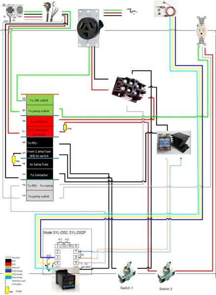
Hey guys - If you can check this out and let me know if you have any suggestions please let me know. This is the layout I am planning for the auberins box (the box is to scale but the components aren't). If I add the herms portion of this, I should be able to squeeze things in and put in another outlet (if needed). I have to check the wiring to see if the PID wiring is any different.

Anyway, have a look and if anything glares out - please let me know.

Thanks again for the help!

Control Panel Box Wiring.jpg
 
something is not right. You have the terminal block labeled "to contactor" going to the SSR, and the terminal block on one side of the 1A fuse isn't connected to anything.
 
Oh.. hang on. I see what you mean. 1A fuse terminal is jumpered to the incoming black line, so it's just the label on the one that says "To Contactor" that should instead read "To SSR", right?
 
You are right - it should say SSR instead of contactor - I screwed that up - but late in the game

edit : unfortunately it isn't easy to change that terminal graphic. My ghetto paint skills were at play for that one.
 
The only thing I see missing is the explicit mention of a ground wire connected to the metal box itself. Just a wire from the right side of terminal block "10" screwed down to the enclosure itself to ground the whole box.
 
Great point - I totally forgot about the ground wire to the box. That is kind of a big deal!
 
Wiring changes if you end up adding a second electric kettle or something would be add a second 240V receptacle, a second contactor, and swap on the ON/OFF toggle switch for the contactor you have now for an ONa/OFF/ONb toggle that will cause one of the two contactors to be enabled for ONa and ONb settings, or both contactors off in the center position. SSR input stays the same, but output feeds to both contactors in the system instead of just one.
 
looks good to me. now.... just follow the advice in my sig and take it to an actual electrician instead of some dudes on the internet. :D
 
I should probably lay in the changes, or put in the hardware the first time. I bought two contactors, so I would just need to grab another outlet and put in another switch with the on-of-on. This way, all the wiring is in.
 
looks good to me. now.... just follow the advice in my sig and take it to an actual electrician instead of some dudes on the internet. :D

Absolutely. And when I build it - someone will be performing QA (i.e. a union electrician). I understand the concepts on some level, and can bend wire. I also can fry my own @ss pretty quick.
 
Basically I wasn't sure if the neutral was good as it is, or if it should be on a switch. I think I have the rest right. Each should get its own ground I think.
 
P-J:

So you would wire the black hot from the SSR, #9 terminal red and one ground from say terminal 11 into the switch and split out those three lines to the two respective plugs?


What about the neutrals from terminals 2 and 3 - these are unnecessary?

And the hot blacks from terminals 6 and 7 to contactors?

Is that switch rated high enough? It says 250V at 15amps, I have 5500W elements; therefore 23-24 amp draw. Or is that 250v and 15amp on each leg?
 
yeah, that switch isn't rated for the current you're going to put through it. Also, I'm sure Walker hasn't seen this because he's a big advocate of not having any switches carrying the entire load of current. I'm in agreement, I'd rather not have to touch anything that has 240V @ 20A+ of current running through it. My rig is BCS based, so I'm even more protected from that as I'm only ever switching 5V at <25ma signals.
 
That was what I thought - but I guess I don't understand the wiring of that switch. you would just run the hots in and split them, and lose the neutrals from the terminal blocks?

Are you saying that I would omit switches 1 and 2?
 
The switch is rated relative to ground. The rated power/voltage is fine for this application as the voltage from either hot line (red or black) relative to ground (the switch housing) is 120V.

This diagram might help - It is with 4500W elements but 5500W would be basically the same:

(Click the image for a full scale printable on 11 x 17" tabloid paper)

 
The switch is rated relative to ground. The rated power/voltage is fine for this application as the voltage from either hot line (red or black) relative to ground (the switch housing) is 120V.

This diagram might help - It is with 4500W elements but 5500W would be basically the same:

P-J, you make great stuff!
I like your NEC disclaimer. You can't be too careful these days, lots of people are trying to get rich from lawsuits.
 
I think I see what you mean, but I am not super electrical savvy. Intuitively it sounds like a good idea to not have switches with the full load. I would think this would help to minimalize risk, especially being around water. Are you confident in the saftey of this setup, in the event of an accident?

The only other issue is... I already have the contactors in hand. I guess as long as they fit in I will probably go that route.

I am sure it will be a mess of wires to neaten up, but as long as it works and it is safe I guess that is my penance for not knowing my electrical stuff.
Some thoughts (IMHO):
You MUST have a GFCI breaker(s) protecting your entire setup.
The switches are controlling resistive loads and therefore are able to handle the full rated load without issues.
You NEED to be comfortable with your setup. So your way is the best way - IF - you are truly comfortable with it.

BTW - I hope I did not come across as being critical. I'm only some guy running his mouth off on the net. ( I do know my stuff IMHO. HA.! Imagine that? In my HUMBLE opinion I know MY stuff. Hope I made you laugh at that.!)
 
I guess I stand corrected, I'm not using that switch so I'll defer to P-J who has way more experience than I do. Sounds like you still intend to go with the contactors since you already have them. They take up more space, but should work well.
 
I think I see what you mean, but I am not super electrical savvy. Intuitively it sounds like a good idea to not have switches with the full load. I would think this would help to minimalize risk, especially being around water. Are you confident in the saftey of this setup, in the event of an accident?

The only other issue is... I already have the contactors in hand. I guess as long as they fit in I will probably go that route.

I am sure it will be a mess of wires to neaten up, but as long as it works and it is safe I guess that is my penance for not knowing my electrical stuff.

My 2¢. In general, the reason for using a contactor is to allow you to use a smaller switch. If the switch is rated for the load current then it will be just as good as using a contactor, electrically speaking. Eliminating the contactor will probably save space in the control box. If you already have the contactor and space for it, use it. It may save you from having to run multiple heavy wires to a hinged front panel. Practical circumstances will be the determining factor.
 
Some thoughts (IMHO):
You MUST have a GFCI breaker(s) protecting your entire setup.
The switches are controlling resistive loads and therefore are able to handle the full rated load without issues.
You NEED to be comfortable with your setup. So your way is the best way - IF - you are truly comfortable with it.

BTW - I hope I did not come across as being critical. I'm only some guy running his mouth off on the net. ( I do know my stuff IMHO. HA.! Imagine that? In my HUMBLE opinion I know MY stuff. Hope I made you laugh at that.!)

Not at all. You guys have really been the only way I could have come into concept on this project - I am grateful for all of your time in effort to stop me from screwing this up.

Should mention:

1. this line will be on a 30 amp GFI breaker from my subpanel in the garage - from 4 outlet to the project box.
2. When the unit is not in use, it will be unplugged.

The switches I have on my current set up are like 3 amp or something I think, but that was what Walker told me I needed based on the way it is set up. Though my "on-off-on" switch will have to be beefed up to at least 25amp I think right? Is that correct?

With your set up it looks like I would need to beef up the switches.

I think I am pretty comfortable with the way it is set up now, but I really, really really will not connect a thing until my bro in law (union electrician) gives me the thumbs up. No matter how impatient I get.


Hope I didn't misrepresent Walker with my switch statement.

And all you guys, really. Thank you for taking the time to share your expertise! :mug:
 
My 2¢. In general, the reason for using a contactor is to allow you to use a smaller switch. If the switch is rated for the load current than it will be just as good as using a contactor, electrically speaking. Eliminating the contactor will probably save space in the control box. If you already have the contactor and space for it, use it. It may save you from having to run multiple heavy wires to a hinged front panel. Practical circumstances will be the determining factor.


Thanks for the information. I think when I started this thread I was going the same way as the switch (I had pulled down P-Js diagram actually), then somewhere in there I decided having the smaller switch was the way i was going to go, probably just based on Walker's or Bruins recc.

The usability aspect will be a little interesting. I went with teh auberins project box in the end, so it isn't hinged. But it will be interesting to creat a good usable control panel face on the front. Since the top and part of the sides come directly off, I am going to avoid wiring anything to the top for ease of access.
 
So P-J and bruin- in the interest of fair comparison. Does my rats nest of a wiring diagram look good to you? or is it lacking?

The one on page 18


I think I will just go ahead and wire it up for two elements. Get it all done now, even though I am not ready for more than the BK install.
 
Also, I'm sure Walker hasn't seen this because he's a big advocate of not having any switches carrying the entire load of current. I'm in agreement, I'd rather not have to touch anything that has 240V @ 20A+ of current running through it.

My 2¢. In general, the reason for using a contactor is to allow you to use a smaller switch.

Yes, I do not like the idea of having the full load run through a switch that I am flipping by hand, but there are other reasons I like using the contactor that just that.

Since you now have an electrical control and not just a physical control that is turning on and off the element, it allows you to implement some other fail safe features.

For example:

The PID has some built in alarm relays on it. One of those is a normally closed relay capable of something like 3A and 240VAC. What you can do (and what I have done on my own system) is take the contactor control signal through that relay before connecting to the contactor coil.

So, it's main feed -> toggle switch for contactor -> NC relay on PID -> contactor coil. Both the switch and the PID have to now agree that the element is supposed to be on for there to be any heating.

I program the alarm paremeters to open that relay if the temp gets above 170*F. So, now imagine that there is an SSR failure and the PID loses control of the heat via the SSR. If the temp gets over 170*F, the PID will open the mechanical alarm relay and the contactor will shut off.

This is a REALLY nice trick for people who brew with a RIMS tube, because you really don't want an SSR failure to result in water boiling inside of a 2x8" stainless steel pipe bomb.

The contactor also gives you the option of adding a timer or other circuitry to make or break the main power feed to the element without relying no the SSR. Like, you set a timer for 60 minutes and that way your boil will absolutely shut off after 60 minutes, even if you aren't there at that moment.
 
So P-J and bruin- in the interest of fair comparison. Does my rats nest of a wiring diagram look good to you? or is it lacking?

The one on page 18


I think I will just go ahead and wire it up for two elements. Get it all done now, even though I am not ready for more than the BK install.
You are premium to go as is.
PLUS: Walker gives you very sound advice. I have NO problems with the contactors.
My only concern (reason for mentioning alternatives) was the room you have available in your controller enclosure.

PS: Walker - Good Job.!
 
Yeah a double thanks Walker - looks like there are some great safety options built into this. I have yet to go through the PID manual, but will being doing so in my down time from my build and the quality check before i plug in. I think it will be well worthe having those extra elements of safety in there. I don't want to be the first guy to die from brewing!

I am sure once I snug up the wires, etc. that box will be fine. Right now the diagram is a little busy because all the wires are neatly laid out. Thank god for zip ties.
 
You are premium to go as is.
PLUS: Walker gives you very sound advice. I have NO problems with the contactors.
My only concern (reason for mentioning alternatives) was the room you have available in your controller enclosure.

PS: Walker - Good Job.!

Thanks, P-J...

I need to say one more thing here. I never suggested that fail-safe wiring to you because it might be a pain in the ass on your system. I don't have the Auber PID with manual mode on it, so I can't use my PID to control the boil strength. I have a separate pulse width modulator circuit to control boil strength.

When my mash is done, I turn the PID off and flip a switch to give control of the SSR to the pulse modulator. The contactor signal still passes through the PID's normally closed relay, but the PID is no longer powered up and cannot shut the contactor off based on temp.

In your system, if you use the alarm relay like I do, you would have to not only switch the PID into manual mode for boiling, but also disable that alarm. If you don't do that, the PID will shut your element off while you are trying to raise the temp to a boil. :D
 
In this diagram:
22294d1300897239-electric-burners-any-builders-out-there-control-panel-box-wiring-two-elements.jpg


This is not how I would do it. You only have one PID and SSR, and (If I recall), you only have enough amps available to run one of the two elements at a time.

So, instead of the one ON/OFF switch for contactor A and one ON/OFF switch for contactor B (which would allow you to accidentally turn on both elements at the same time), I'd use a SPDT-CO switch. Single-pole, double-throw, with a center-off position.

That switch will have three connections on it. one for incoming feed from the 1A fused hot line and then one output to contactor A and one output to contactor B.

With the switch in the center position, neither contactor is enabled. With the switch flipped one direction, contactor A is on, with the switch flipped the other direction, contactor B is on.

No way to accidentally turn on both contactors (and both elements) at the same time.
 
Well haha for now I think that the set up, even with that fail safe not necessarily convenient, more than meets my needs. Right now I will be surprised if I have an HLT and a BK hooked up for a while. I basically need a boiling element, and an element that would heat my HLT to strike temps. I don't even have an HLT yet, and have been using my boil kettle for that task and my kitchen stove for sparge water. i.e. herms is a long way off!

However thanks for explaining it!
 
With the system you are about to put together (one contactor, one element, one PID, temp probe, pump outlet), the only thing you have to do to make it a HERMS system is put your immersion chiller down in the kettle and pump wort through it.

I have been brewing on my HERMS for a year now and I only have one electric kettle. I don't see the need to make a dedicated electric HLT. The only time I even need a third vessel is when draining my first runnings to the boil kettle (there's two vessels) and needing a place to hold some hot water (there's the third). At no other point is there a third vessel involved.
 
In this diagram:
22294d1300897239-electric-burners-any-builders-out-there-control-panel-box-wiring-two-elements.jpg


This is not how I would do it. You only have one PID and SSR, and (If I recall), you only have enough amps available to run one of the two elements at a time.

So, instead of the one ON/OFF switch for contactor A and one ON/OFF switch for contactor B (which would allow you to accidentally turn on both elements at the same time), I'd use a SPDT-CO switch. Single-pole, double-throw, with a center-off position.

I see your point here. Two questions:

1. wouldn't the breaker in the subpanel just trip with two elements accidentally on?
2. Do you have an example of that switch you could pass a link from?

I am upgrading my subpanel to 100amps, but was only planning on putting in a 30 GFI breaker for the brew panel.
 
Back
Top