Questions on RIMS build

Homebrew Talk - Beer, Wine, Mead, & Cider Brewing Discussion Forum

Help Support Homebrew Talk - Beer, Wine, Mead, & Cider Brewing Discussion Forum:

This site may earn a commission from merchant affiliate links, including eBay, Amazon, and others.

bmurph

Well-Known Member
Joined
Mar 31, 2011
Messages
84
Reaction score
0
Location
Baton Rouge
I have some questions about wiring a RIMS, sorry couldn't find the specific info I'm looking for on the forum. Most wiring schematics I look at show everything as belonging to one big series of circuits and converging into a single 3-prong plug. I'm wondering if the pump needs to be included in all of that. Could I keep it separate from the rest of the wiring and just turn it on and off manually?

Also, which components will need to be grounded? I assume the SS hardware, but what about switches, electrical components?

And I'm using a 25A SSR- will I need a heat sink?

One last thing--wiring this whole thing up doesn't look too bad, but I'm unsure of the connectivity; there is good bit of variation in the schematics I've viewed. Would anyone mind sending me pics of their own schematics?
 
Also, if I was going to install switches/lights, should they be on the hot or neutral side of the component?
 
I sized my ssr around 3x bigger then my heating element (over kill but small increase in price, I run me freezer with the same size ssr...) , but if yours is pushing 12 or 15 amps you should be okay without a heat sink - mine never seem to get very warm. You could attach it to a piece of aluminum if your worried about it. Ground everything metal! So ground your RIMS tube, switches, etc. Run the hot (black) wire through the switch, white is common - connect them all together. I wired my heating element and pump through the same box so that the heater could not be turned on without the pump being powered too. I'll try to draw a schematic later.
 
bmurph,

What element are you using - 120V? 240V? and what wattage?
Also what is your power source? (Amp and voltage rating)

I probably already have a diagram drawn that might help you.

P-J
 
bmurph said:
Also, if I was going to install switches/lights, should they be on the hot or neutral side of the component?

I don't think you should do any electrical work!
 
bmurph,

Please ignore the bashing. I want to help. Help me help you.
Again:
What element are you using - 120V? 240V? and what wattage?
Also what is your power source? (Amp and voltage rating)

I probably already have a diagram drawn that might help you.

P-J

PS: Everybody... We all start out somewhere. He reached out for some help. Please give it to him instead of bashing him.!!!!
 
I wouldn't consider this bashing. Electricity is very serious and his question led some to believe (including me) his knowledge is just enough to injure himself.
A simple understanding of switches and other components is a necessity especially when you are discussing electric brewing.

bmurph: a switch typically has no neutral. It's a valve opening and closing a source of power. A relay is a switch powered by a coil (a primary switch).

Lights require a hot and neutral.

Much to learn...

Ignorance is not a fault. It's just a lack of knowledge that can be attained. Stupidity is disregarding knowledge attained.

Your safety is our first concern
 
I agree. This isn't that hard but there still is plenty of opportunity for things to go wrong. This is much more complicated than many other DIY electrical chores. You need to correctly wire everything, but you also need to choose the correct AWG, voltage, switches, plugs, box, etc, etc. There is also the whole (different) mindset required when testing and trouble shooting (there will always be trouble) higher voltage circuits.

Obviously it isn't my place to decide what you can and can't do. You have to ask yourself, is this worth it?
 
Who's the next contestant on you you bet your life? Not picking on any one this is a reality check. If you have no idea how to wire a simple switch you need to a lot of learning.
Good luck.
 
Who's the next contestant on you you bet your life? Not picking on any one this is a reality check. If you have no idea how to wire a simple switch you need to a lot of learning.
Good luck.

I don't know what HBT would do without your wisdom.
 
Bmurph. Ignore the nay sayers on this thread. Ask if you have questions (which you are). Do your research and become familiar with electricity and it's dangers. When you are comfortable go ahead and wire it up, but before applying power have someone with an electrical background look it over (it might cost you a few beers) but it will be worth it. One more thing.... When you start your wiring keep it neat unlike a lot of the hack jobs that are posted here. Good luck.
 
Bmurph. Ignore the nay sayers on this thread. Ask if you have questions (which you are). Do your research and become familiar with electricity and it's dangers. When you are comfortable go ahead and wire it up, but before applying power have someone with an electrical background look it over (it might cost you a few beers) but it will be worth it. One more thing.... When you start your wiring keep it neat unlike a lot of the hack jobs that are posted here. Good luck.

I also agree there is no bashing going on here. If you're going to pay someone to "check" it for you, then for christsakes, just pay them to do it, and look over their shoulder if you want to learn. Most will be happy to explain what they're doing as they go. Trial and error is not a very good way to go about learning electrical systems.
 
While I'm self taught I agree. You could learn a lot safer, a lot faster, and hopefully not pick up as many bad habits by consulting someone knowledgeable. BUT, what if you don't know anyone? It could be real expensive to pay an electrition to come out and help and may (most) would probably be leery of anything too far from the norm. I'm sure you could pick up a book from a home store and get most of what you need.
 
jbaysurfer said:
I also agree there is no bashing going on here. If you're going to pay someone to "check" it for you, then for christsakes, just pay them to do it, and look over their shoulder if you want to learn. Most will be happy to explain what they're doing as they go. Trial and error is not a very good way to go about learning electrical systems.

This thread is not about paying other people to do the work for you. It's about helping a fellow home brewer. I agree that "trial and error" in not a good way to learn about electricity. However making educated decisions about wiring is ok.
 
There has to some liability in offering advice to someone wiring 30 to 50 amp control panels. Proper conductor size, proper grounding and bonding, over current and ground fault protection, and what about the tools to build and troubleshoot. There is a lot more than just throwing some parts in a box. You go ahead and tell them that its easy.
 
I don't know about the liability of advice given. It's best to assume any information gained on the internet is someone spitballing anecdotes. Treating it as more reliable than that can be dangerous. Of course, with enough reading you can gain a little more confidence if several sources confirm it but even then it's hard to trust.
 
mux said:
There has to some liability in offering advice to someone wiring 30 to 50 amp control panels. Proper conductor size, proper grounding and bonding, over current and ground fault protection, and what about the tools to build and troubleshoot. There is a lot more than just throwing some parts in a box. You go ahead and tell them that its easy.

I don't think I used the word easy. I do agree with you but this isn't rocket science. Please see a previous post where I recommended someone with an electrical back ground to look over his work. It is up to the individual to determine if they are capable of performing the work. If they are not then they need to do research and ask questions. (the purpose of this forum?) I accept no responsibility if someone electrocutes them selfs due to their ignorance.
 
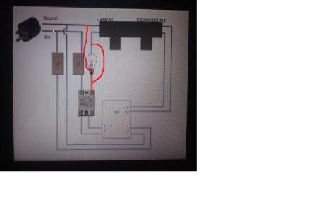
My element is 120 V 1440 W low density, and this might sound dumb but as far as a power source I was planning on plugging it into a standard 3 prong outlet. I want everyone to know that I don't plan on just throwing parts in a box, I will not sit down to work on this without doing my homework (why I started this thread), and I have an engineer buddy whom I've enlisted the help of (only he's more mechanical than electrical). I am not taking this lightly; I understand the risks involved. With that said, if I ask a stupid question, the reason is a lack of knowledge rather than ineptitude at learning, and I would prefer an explanation to a dismissal. Everyone in the know had to build their first circuit at some point; I appreciate those who understand this fact. Ill take a risk and include in this post my first rough schematic; I realize that its missing ground wires. What I want is a switch to control power to the PID, one to power on the SSR and heating element, and a light that goes on and off with the heating element. I know they're prob not in the right spots in my schematic; can someone tell me where they should go and why? Also, as someone has mentioned, info from the internet may not be the most reliable; does anyone know of a book or other source I can trust that can teach me what I need to know?

ForumRunner_20120521_030924.jpg
 
Your drawling looks okay except the light would be wired in parallel with your heating element. So one side (the side that goes to the center of the bulb) will go to the same wire as the heating element, the other side would go to the neutral (negative) wire. You might consider skipping the 120v light and wiring an led to input of your ssr or better yet use a small 120v pilot light (which for all I know you plan on doing). BTW lights (except LEDs) don't have a polarity and can have positive and negative hooked up either way, your heating element is probably this was also. I understand the picture you included was for demonstration purposes and you may be using other things but have you considered plain old toggle switches? You can get nice water resistant rubber covers for them and they take up much less space. I recommend you use 14 or 12 awg stranded hookup wire and standard wire lugs (blue or yellow depending on the wire you have) for the 120v side, the low voltage side could be nearly anything, 30awg would be big enough (but hard to deal with because of its small size) I recommend ~22 awg or so. You can do this. Good luck!
 
Let me see if I understand about the light: the path from the SSR output should be split, with one side going to the heating element and the other going to the light, then they rejoin into the neutral wire? And yes, I had in mind something like a pilot light, just didn't know what to call it. And are you saying it would also work if the light were wired between the PID and SSR? If I did that, are there new considerations to be aware of? Would the same light from before work for this too?

I'm not opposed to using plain toggle switches; I've seen ones like those mounted in toolboxes and it looks pretty neat.

And since my SSR is 25A, should I be prepared to draw that much current and choose my wires accordingly? 12 awg is only good up to 20 amps right?
 
Look at the picture.

If you wire something between the PID and the SSR it needs to be low voltage like an LED. If you use an LED you need a resistor something between 270 - 470 ohms would be fine (I use 330 ohm 1/4 watt resistors) you can buy them by the 100 for a dollar or two on ebay or get them from radio shack. You can get LED's with threads for mounting from radio shack or on line for little money.

"And since my SSR is 25A, should I be prepared to draw that much current and choose my wires accordingly?"

As far as amp load you can calculate it: amps= watts / volts. So 1400 watts / 120 volts = about 12 amps. 14 gauge wire is fine for 12 amp service (especially at lengths of a foot or two), 12 gauge would be overkill but wouldn't hurt a thing. (like you said 12 gauge in most cases is good to 20 amps). Your SSR will provide up to 25 amps (theoretically) which would be good for 3000 watts, but only what is flows through the heating element will flow through the SSR, this will be about 12 amps. The outlet your plugging into and the wires in the wall will (probably) not safely carry 25 amps so IMO there is no point in wiring everything for 25 amps (ie 10 gauge).

wire.jpg
 
This is what I did (mostly). Here is a circuit. BTW: I am NOT an electrition and totally and completely knowledgeable about electricity. Use this at your own risk.

RIMS circuit.jpg
 
This thread is not about paying other people to do the work for you. It's about helping a fellow home brewer. I agree that "trial and error" in not a good way to learn about electricity. However making educated decisions about wiring is ok.
Edit: Your post encouraged him to hire somebody to check his work for him. Mine merely encouraged him to hire that same person to help with the build.

I love the DIY nature of this forum and this community in general. I also am not an electrician, but don't think this stuff is unlearnable. I just think one's first electrical project involving 25+ amps of electricity probably merits the oversight of someone who knows what will and will not kill you.

I learned electricity from a book, but I put it into practice by hiring someone who was already an expert. I'm not encouraging anyone to abandon his diy brew stand by any stretch...merely encouraging him to do what I did, and thought was prudent.
 
If I got a lighted switch for the high-voltage side, would it come on and off with the heating element, or would it just stay on the whole time? I'm wondering if I even need a separate light. Anyway here's my next schematic with the LED and resistor if I need them. I assume the black and white wires will be fine with 14 awg, but will 22 awg work for the rest?

And I would ground: both switches and the RIMS tube, anything else? Can I assume that 1 ground will take care of the whole stainless tube structure? I read that although you would assume current could spread across the entire element since it's all metal-on-metal, separate ground wires are needed for each piece of hardware. Is that true?

View attachment 2012-05-23 03.44.58.jpg
 
Only one light is needed, either light would only come on when the element was energized. You show the LED wired incorrectly, as shown neither the SSR or the LED would turn on. Look at the way I drew it. 2 wires go from the PID, they also go to the led, you show the LED inline. The SSR needs to see both positive and negative with nothing in between. The LED needs to see both positive and negative too but needs a limiting resistor inline (it could go on either the pos or neg side, doesn't matter). Note too that the LED will only work one way, there is a pos side and a neg side, the neg side has a flat spot molded into it.

As far as grounds are concerned, I would ground any metal object that comes in close contact with 120v. Ground the outlet too. I would assume that there is good contact between pipe fittings that are solidly (metal to metal) joined. If you are connecting the heating element to the tube with a tri clamp there is still a metal to metal connection when its clamped, I'd call that good. Others may not, its really up to you how far you want to go to try and guarantee safety. You could jump a wire from fitting to fitting but that sounds like a PIA, unnecessary, and messy.
 
Before I attempt to power anything on, I will have a professional check it over.

I think I might opt for the lighted switch if it will serve the same purpose and just drop the LED. I'll save lighting for another day, but I still want to understand. Would I just put the resistor and LED in parallel with the SSR like this?

It took a minute for your drawing to sink in, but I think I get it. I hadn't seen someone install their own outlet in the system; I assume it's a safety precaution? And I assume all your ground wires converge into the green wire of the 14/3 cable that plugs in the wall? Their path isn't shown (I'm guess that's convention), so I just want to be sure I have it right.

And I want to clear up some terminology: I keep reading about the "high-voltage" circuit containing the heating element and the "low-voltage" one containing the PID controller, but they're parallel circuits that share a power source. I thought the voltage drop was the same across circuits in parallel, and both sides would get 120V. Would it be more correct to say "high-current" and "low-current?"

View attachment 2012-05-23 17.03.54.jpg
 
You definitely don't need both the LED and a pilot light, but it could help with trouble shooting. It's just more information.

You show the LED wired correctly.

I like to use a regular outlets because they're cheap, safe, and convenient. That way everything just plugs and unplugs. Simple. All of the ground wires would join with the green wire as you say, ground is shown on a schematic as that upside down triangle of smaller and smaller lines. Their path is often omitted just to simplify the drawing. The ground is really just a redundant neutral wire (the negative, white wire), it provides a second (emergency) path to ground to hopefully stop you from becoming that path (ouch!). That's why you want anything with a hot wire running to it to have a ground wire running to it as well, safety first.

All of your switches, the heating element, and half of the SSR are high voltage (120v AC). We could talk about the current but we're not (the heating element at 12 amps is high current, a pilot light at less than.25 amp is low current). The PID output to the SSR (the input into the SSR), the LED, and the thermocouple leads are all low voltage (~5 volts DC). High voltage could kill you as well as any low voltage equipment it touches. Low voltage will not hurt you but your static electricity could hurt it!

I like to wire the power to the pump from the same box so that the heating element cannot be powered unless the pump is running. This just might save your heating element. Plus its nice to have an on off switch for the pump.
 
Oh BTW I guess your PID sees 120v on pins 1 and 2 as power in. I don't know anything about PIDs actually! I built my own with a Picaxe micro controller and a LCD screen I had laying around. For what its worth.
 
First off thanks for all your help so far; I would be lost without somebody to explain all this stuff. And I was thinking of using pigtail connections to join my wires, but is there a better/neater/safer method you may have used?
 
I tend to favor run of the mill crimp connectors. I also often use crimp on pig tail connectors (almost like a crimp on wire nut). You can use all sorts of things really. Wire nuts are fine. I would use whatever you are most comfortable with. No worries. One thing I really like to do is after I have everything full finalized, I hot glue the wires in place. This saves so many head aches you can't believe it.
 
Ok yeah I was planning on keeping it neat. I think just a few more questions and I should be good.

How did you connect your ground wire to the RIMS tube? Is soldering an option?

The SSR is mostly cased in plastic but the bottom is metal; will that need a ground?

Will I need to insulate the terminals on my heating element and switches? How do I do this?

And is it a bad idea to put the RIMS tube inside the toolbox? A member of the club I belong to does this without problems apparently, but I feel like it would get hot in there.
 
Soldering is an option for grounding your RIMS tube but IMO it isn't worth the trouble. I was able to just put the ground wire under a hose clamp and clamp it on, it looks nicer than it sounds. To insulate the heating element wires I got a large pvc pipe cap, drilled a hole in the end so the wire could go in and force threaded it over the heating element. Then I sealed it with silicone calk. There is no need to ground your ssr because you are never going to touch it. Same with insulating the wires on your switches, you should ground your switches, ans waterproof switch boots would be a good idea too. You could put your RIMS tube where ever you like, I insulated mine and I strap it in place next to my mash tun. It should be fine in a tool box.
 
There is no marking because it doesn't matter. connect one lug to the hot/black/power wire from your ssr and one lug to the neutral/white/common.
 

Latest posts

Back
Top