BCS 462 propane controller help: accountant trying electrical

Homebrew Talk - Beer, Wine, Mead, & Cider Brewing Discussion Forum

Help Support Homebrew Talk - Beer, Wine, Mead, & Cider Brewing Discussion Forum:

This site may earn a commission from merchant affiliate links, including eBay, Amazon, and others.

The_Gerbil_Brewer

Well-Known Member
Joined
Feb 27, 2013
Messages
75
Reaction score
8
Location
Boston
I've been searching through a lot of topics on automation and I think the discussions most similar to what I'm looking to do are much more complex than needed. Without any prior experience with electrical work (besides building a stir plate) I'm not able to take what has been explained in those discussions and apply it to my project.

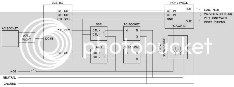
I'm building a single tier, 3 burner HERMS brewstand that will be run on propane. I'll be utilizing the BCS-462, 2 Honeywell Y8610U6006 gas valves with intermittent pilots, and 2 chugger pumps. While I may expand the level of automation in the future, at the moment I'm looking to have the BCS do the following:

- heat strike water and HLT water at the same time
- Maintain HLT water at prescribed temps
- cycle pump on and off to circulate mash liquor through HERMS coil
- record BK temps (plan to manually ignite but would like the BCS to collect data on boil)

I'd like the control panel to have the following characteristics:

- If possible have one plug powering everything (standard GCFI household outlet)
- Not modify pump power cords (i.e. have them plug into outlets controlled by BCS)
- CAT5 outlet on outside of control panel for me to plug my laptop into (which will connect via WiFi)
- Be able to control manually (saw 3 way switches being used in other BCS builds: Off, Manual on, BCS-controlled) in case BCS failed, internet connectivity issues, etc.
- Nice to have, but not necessary: lights indicating when each of the 4 elements is running (2 pumps, 2 gas valves)

I plan to keep the gas valve modules in a separate NEMA enclosure to utilize the wiring harness included with the kits (not very long) and also in hopes of avoiding interference with the BCS. I have a logical thought process but, as stated, have virtually no electrical experience so any and all info/advice is greatly appreciated (e.g what gauge wire, transformer/SSR specs, etc)

I've learned a ton so far through these forums and will make sure to pay any advice given forward. Thanks in advance for any assistance!
 
Last edited by a moderator:
Seems excessivly complicated. I did not look at it too closely. But you have Solid state relays energizing a 120 VAC relay coil. A 120 VAC relay turns on a 2nd 120 VAC relay?

I do not see a master ON-Off switch. I do not think this thing will urn on.

Your AC comes into the box via 3 relays, 1 ea for Hot, Nuetral and Gound. Do not use a relay on the ground, the ground should never be switched off. If you want to switch the Neutral, you can do that on the same DPDT relay. In fact I recommend it. safer that way.

The sockets for the pumps are not ground fault type. I would conider that a must in a brewery.
 
After giving this thing a second look, I see more problems. You show a DC to DC converter getting fed by an AC signal. You connect DC ground to once leg of the AC transformer. Huh?

I have to be brutally frank. With the mistakes you are making, I suggest you stay away from this project. Your understanding of basic electronics and electricity is low to a dangerous level. 120 VAC and a very liquid environment is not a good combination for the neophyte to learn.

Hi Rufus. I appreciate the frankness and you're spot on - I have very limited knowledge of electrical. That said I don't have any intentions of abandoning the project, unless someone is willing to build this for me for cash or brew (If you are message me :mug:). I'd think it's safe to assume most people on HBT building semi-automated brew stands don't have extensive knowledge in welding, HVAC, and electrical systems and therefore work with this great community to help them sort it out. I have no intention of even beginning this build until I feel confident of all the components and how they need to fit together.

I was hoping to find something on HBT that clearly documented the components and assembly of this (as there are for stand builds and some propane manifold designs) but wasn't that lucky. Most of what I found was schematics for PID controllers with honeywell valves or all out electric breweries. Instead of asking a million questions I figured I could utilize what I found on HBT to come up with a schematic that would hopefully be in the ballpark. From your response it's clear I completely missed the mark - I definitely appreciate that feedback. So my next step will be reading posts on HBT meant for neophytes to better understand electrical (I'm currently reading the "Electrical Primer for Brewers" post which is very helpful thus far) as it's apparent my use of other's schematics did not work and I need to get a better understanding of basic electrical work and each component in a system.

Thanks again for the feedback - hopefully my next go-around will be much closer to what I should do.
 
Let me see where I can help you out.

For 120 VAC, all you should switch is the hot leg of AC. You can connect all Neutral lines together. Same for the Ground lines, connect them together. No reason to switch both the Hot and Neutral lines.

You need a switch as the first thing after your AC line comes into the box. It has to be a mechanical, On/Off Switch. You cannot use a relay. With the power off, there is no source of power to energise the relay.

With the equipement you have selected, looks like you need 3 different power supplies. You cannot mix and match them, or connect them together.

1. 120 VAC
2. 24 VAC
3. 12 VDC

For the 12 VDC power supply, I suggest you get a wall wort an off the shelf 120 VAC to 12 VDC adaptor. Going from 120 VAC to 24 VAC to 12 VDC does not make sense. As I said, the 12 VDC supply you selected, I doubt it will work with an 24 VAC input.

For your 120 VAC power sockets, I strongly suggest you use 120 VAC Ground Fault Interupt (AKA GFI) style AC sockets. They can literally save your life.

No reason to have the solid state relay (SSR) turn on the 120 VAC relay. Have the SSR switch turn the power to your AC socket. The input + (plus) terminal goes to your BCS, the - (minus) terminal goes to your 12 VDC ground.

I am not familiar with the Honeywell unit. What is the input power? Is it 24 VAC? If so, what do the relays do? Are those relays to turn the power to the Honeywell On/Off? No reasonto do that. In fact it may delay your burner turning on.

Why do you need to turn the Honeywell units On/Off seperately? Why not turn them on and off at the same time? If they are 24 VAC power, hook them up directly to the 24 VAC transforner. When the 120 VAC power comes on, the transfomer powers up and the 24 VAC transformer will turn on the Honeywell units. Turn them on at the begining of your brew session, turn them off when you are fisnished. Their stand by power consumption is very low.

I am not familiar with the BCS unit and the Honeywell unit to know how the two interact and the control interfaces. Good luck in that interface.

It would probably help if I provided some details in my intention. I am building a single tier HERMS brew stand and am running temperature probes from the HLT and Mash to the BCS. Based on set points the BCS would turn the 2 propane valves and 2 pumps on/off. I want to control the gas valves separately as I mainly want to fire the Mash tun to get to my strike temp. Depending how the system operates I may also use the mash burner to more quickly mash out or step-up and possibly help maintain mash temps in the colder months. The HLT would therefore fire more frequently than the mash tun to maintain and raise the temp of the HERMs coil (primary way I intend to hold/step up mash temps). I know there are multiple ways to skin the HERMs cat, but feel if I'm going to automate 1 pump and burner, automating the second pump and burner gives me more flexibility in determining what HERMs process works best for me.

The pumps are both 1.4 amps and the maximum load for the honeywells is 1A for the pilot and 2A for the Main. So if I’m thinking about this correctly, if both pumps were on and both burners were triggered (main and pilot) the total current needed would be 8.8 Amps. I would therefore need an on/off switch rated to at least this level. If my understanding is correct it seems that either of these (switch 1 switch 2) would be sufficient - 110V up to 35 amps and 110V up to 16 amps respectively.

I was hoping to run everything off one power line, but to keep it simple it seems best if I simply use the power adapter that came with the BCS and plug it into a separate outlet. You state that I wouldn’t be able to run the 120VAC and 24VAC on the same line – does that mean running a main 120V line into the box and then splitting it 3 ways (electrical twist nuts), with 2 going to 110V outlets for the pumps and 1 going to 24VAC transformer not be okay? Would I need to therefore run 3 lines from the house to the box (1 for the BCS, 1 to the 24VAC transformer for the honeywells, and 1 for the 2 outlets for the pumps?

I was planning on connecting the power to the control box to a GFI outlet in my apartment. Does utilizing GFI outlets within the box add additional levels of protection? If so, I’ll totally do that. My original thought was that if water came in contact with the electricity it would cause the main GFI to trip. If that’s the case then would making the pump outlets GFI add the advantage of tripping the internal GFI outlet leaving power running to the other components (since the house GFI wouldn’t trip)?

The BCS wiki states "Discrete Outputs are rated at 5VDC up to 20mA each. These outputs are sourcing, meaning that they are 5VDC when the output is ON. The BCS is designed to control relays, and not to drive high current loads. A typical application is to use Solid State Relays (SSR) for this purpose." which suggested to me I would need a total of 4 SSRs to independently control each pump and burner. The attached diagram is from this HBT discussion which suggested the transformer to step down the voltage from the power source (120V) to the Honeywell valves (24VAC).

Based on your advice, what I've learned through further electrical reading, and the BCS wiki, I've modified the original attempt. Is the attached more in the ballpark of what I should be doing for the control panel? Additionally I think I should add in fuses, which was discussed in this great post.

Thanks again for all the info and assistance!

Gas_Control.jpg


View attachment Schematic Draft v2..pdf
 
GFI sockets. (for this discussion think of 120 VAC electricty flows from hot to neutral, like DC) The GFI looks at how much current goes out of the Hot terminal and compares that to how much current comes back into the Neutral terminal. If it sees more current leaving than comes back, it assumes the missing current is going through you and shuts down the circuit. If you put the entire system on a single GFI, you are more likely to get a false alarm and have your entire system shut down, unnessicarily. I would make each socket it's own GFI. GFI sockets are not that expensive.

If you plug the BCS power supply into the same AC socket as the rest of the system, you should be OK. AND if the BCS and the SSR relays are the only devices in the system

You need some help on how relays Let me see what I can do.

Let's start with how switches work. A relay is a switch, but instead of your hand moving the switch, a voltage source makes the switch.

Let's say you had a light bulb and you never wanted to turn it off. Wire one side of the bulb to hot, the other side of the bulb to neutral. The bulb lights and never turns off. If you want to use a switch to turn it on and off, put a break in Hot lead between the fuse box and the bulb. Put a switch in the beak. As the switch opens and closes the connection between hot and the light bulb, the bulb goes on and off. The neutral connection stays a straight connection.

Note how both sides of the switch have the Hot voltage. Note how you only have to switch (open/close) one of the two wires. Typically you switch Hot for AC and +/positive for DC.

An SSR relay has 4 teminals. The + control terminal on the SSR relay goes to a GPI output on the BCS. The - terminal on the SSR relay goes to a GND terminal on the BCS. When the BCS wants to turn something on, it puts a voltage into the + terminal on the SSR relay. When the SSR relay sees a voltage on it's input it closes the connection between the output terminals. Notice on your drawing the little switch symbol between the output terminals. This is what it does.

How do you use the output terminals? On one side (say terminal #1 on your drawing) you put a Hot lead. You run a wire from terminal #2 to hot input on the device you want to turn on. On the neutral terminal (of the device you want to turn on) you run a wire directly to a neutral 120 VAC.

The connection between the output terminals on the SSR relay opens and closes (like a switch) when you apply and remove voltage on the input.

If you wanted to turn on a light bulb with the BCS, wire the inputs as I described. Connewct the Hot to Pin 1 on the SSR output, connect Pin 2 to one terminal on the light bulb. Wire the second/open terminal on the light bulb directly to Neutral.

Next comes that mess you have with the SSR, the coil relay and the Honeywell controller. What ever it is you are tring to do, your schemtic ain't right. Same goes for that nightmare you have associated with the SSR relays, coil relays and AC sockets.

First off, are you sure you want to turn the power to Honeywell On and Off? Typically, devices like this, you power the device and it stays that on. Then put a trigger into the controller to make do what you like.

I would expect that you power the Honeywell and then use the BCS GPIO to trigger the burner on and off. You want to take the output of the 24 VAC transformer and run the 24 VAC directly into the Honeywell. I see no reason to switch the 24 VAC into the unit. Use the BCS to act as a substitute thermostat to tell the Honneywell device to fire the burner.
 
Gerbil. Here is a high level diagram of what I believe you want to do. I do not show the probes into the BCS. When ever your BCS decides to turn something on, this gives you the path to do so.

As said before, the BCS replaces the thermostat on your wall.

I am not familiar enough with Honeywell device to provide details beyond what I show here, but I am pretty sure you want to power up the Honeywell with 24 VAC at the begining of your brew day and leave it on. You do not want to power cycle the Honeywell by way of the BCS.


Gerbil1_zps9qobmoa6.jpg

Thanks Rufus - very much appreciated!
 
Back
Top