ReuFroman
Well-Known Member
I have been spending time placing and thinking and drawing and then redoing. I think I need the collective mind to show me the way to glorious ebrewing utopia.
Which option worked best for you or you wish :
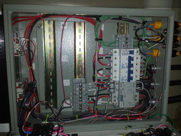
1) long rows of din mounted components
2) short rows with segmentation of parts plated together. Breakers and coils on a rail. All power on another.
3) I just went for it and it worked
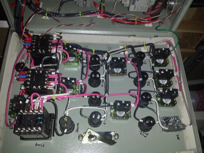
If you could send a pic of your internals (keeping in mind safely) along with what your theory was behind the design. It would help me out a bunch. I start my cut, drill, and wire next week.
P.s. I know this was brought up on the show me your panel thread but I thought this would be better broken out for future use.
Which option worked best for you or you wish :
1) long rows of din mounted components
2) short rows with segmentation of parts plated together. Breakers and coils on a rail. All power on another.
3) I just went for it and it worked
If you could send a pic of your internals (keeping in mind safely) along with what your theory was behind the design. It would help me out a bunch. I start my cut, drill, and wire next week.
P.s. I know this was brought up on the show me your panel thread but I thought this would be better broken out for future use.
 . I wanted to get mine finished and test it before fretting too much about what the BEST way was. I wanted the WORKING way first! Its always exciting to hear that *clunk* of the contactor firing and no smoke showing up.