Suggestions for controller

Homebrew Talk - Beer, Wine, Mead, & Cider Brewing Discussion Forum

Help Support Homebrew Talk - Beer, Wine, Mead, & Cider Brewing Discussion Forum:

This site may earn a commission from merchant affiliate links, including eBay, Amazon, and others.
That looks AWESOME! I'm going to attempt the exact same thing! I may end up going with a tool box so I have a little more room. Would it be ok to use a plastic tool box?
 
That looks AWESOME! I'm going to attempt the exact same thing! I may end up going with a tool box so I have a little more room. Would it be ok to use a plastic tool box?

Thanks! I'm really excited about it.

Regarding the box, I think metal is preferred but I'll defer to those more knowledgeable on the subject.
 
Do you have to have GFCI?

If so, my current plan was to tap into my dryer run which is on the same side of the house as my brewery. That being asid, I highly doubt that I have a GFCI breaker installed in my main panel. If I was to use GFCI do I need to run cable from my panel which is on the other side of the house, or can I still tap into the Dryer circuit?
 
Quick question. I found a way to plug my sight glass hole and have everything working. It's heating super fast! It got somewhere around 6 gallons up to 150 degrees in around 7-8 minutes. Without my sight glass I'm not exactly sure how much is in there though.

Problem. When at room temperature last night my probe was reading within 1.5 degrees of my lab type thermometer. While heating it seems to be closer to 20 degrees behind. I'm not sure exactly what's going on with that.


Thanks.
 
Do you have to have GFCI?

If so, my current plan was to tap into my dryer run which is on the same side of the house as my brewery. That being asid, I highly doubt that I have a GFCI breaker installed in my main panel. If I was to use GFCI do I need to run cable from my panel which is on the other side of the house, or can I still tap into the Dryer circuit?
I absolutely believe it is critical that your brewery be protected with GFCI power. You are dealing with electricity in a wet environment and your life will depend on it. Do NOT take a risk with this.

You can provide GFCI protection easily by going to HomeDepot and buying this GE 50A 240V Spa Panel GFCI for $49.00 and then wire it up this way:

power-panel-6.jpg


Use a 3 wire dryer cord for its input and then install a 4 wire outlet for the output to your brewery.

Buy this Leviton 2716 30-Amp, 125/250 Volt, Flanged Outlet to mount in the spa panel. Then use a 30A 4 wire dryer cord for the input to your electric brewery controller.

The SPA panel will provide your GFCI protection & the mains panel will provide the 30A breaker for your rig. Plus you also develop the equipment ground while doing it without having to rewire your house. Another added benefit is the panel is a lot cheaper than just buying a 30A GFCI for your mains panel.

Hope this helps and please stay safe.
 
Last edited by a moderator:
After checking it some more it doesn't seem nearly as off. After reading a bit I played with the Pb setting. I have it set at 3.5 now and it seems about on target. Not sure if that's excessively off or not. Maybe it was the response time throwing me off. I know I don't want to mess with taking the connector out of the box and redoing it.
 
I got it dialed in it seems. I guess I just didn't know what I was doing before. I have the Pb set to 3 and it seems dead on now. I set t to 2 if I remember right and hyst to 2. I initially set P to 1 based on some reading here but I ran an autotune and it set it to 80.

I tested both outlets with my hlt since I need to replace the element in th BK and replace both sight glasses. Both element outlets worked perfectly

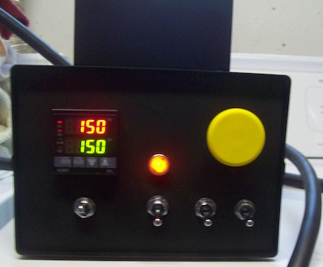
It held 150 in automatic mode and boiled in manual mode without a hitch. I took some pics. My location's boiling temperature is around 210.4 degrees, so at the moment the sensor is reading between 210-211 (switching between them). I may fine tune the Pb setting a bit more later if needed.

It boils just like I expected. I think it took around ten minutes to boil from 150 degrees.

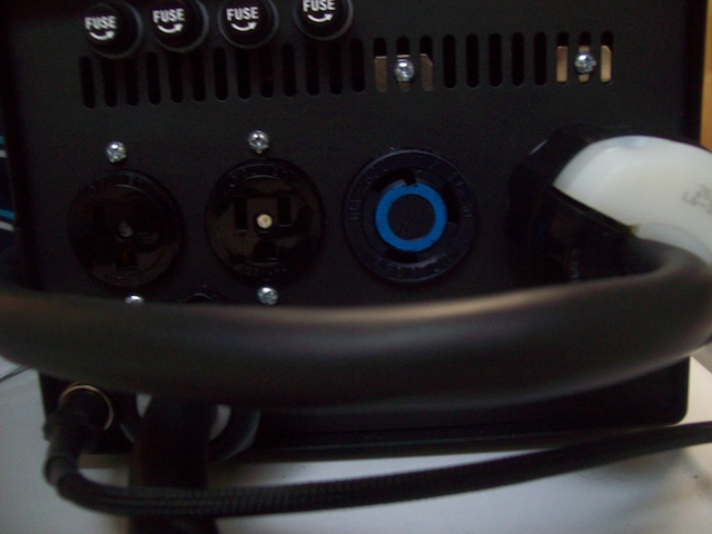
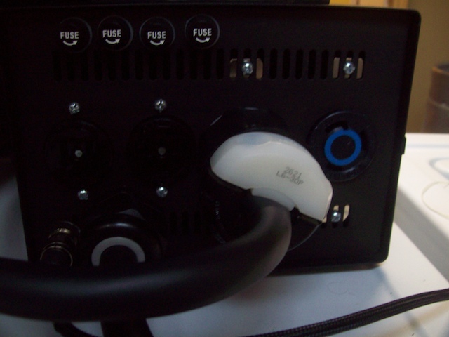
Pic 1: plugged in to the HLT outlet
Pic 2: holding at 150
Pic 3: boiling in manual mode
Pic 4: BK outlet
Pic 5: Boiling! No pulsing. Just a nice steady boil.

Now I just need to prepare my brewing area and I'm in business!

hlt outlet.jpg


holding temps.jpg


boilingmanual.jpg


BK outlet.jpg


boiling.jpg
 
Yes it's a 4 [plug dryer plug, but I will be tapping into a junction boxin the basement. How do you tell if the breaker on the main panel is GFCI or not?
 
I've been researching different electric builds for a while and this design is exactly what I'm looking for. My Father in-law used to be an electrician so he is going to help me get a new circuit setup with a GFCI for this. I think i'm going to use the second design with two indicator lights except without the timer.

I noticed you only have one RTD input, do you move the probe cable between the two vessels?

If I used that same box could I fit the SSR heatsink inside?

Looking at the diagram the only other thing that I was unsure of are the terminal strips. This may be a dumb question but how do these work? I thought it connected the two connections across from each other. I also see that there are four on the diagram and only 3 on your build, but larger ones.

Thanks.

For the RTD, you only really need one since you're using the PID in manual mode for the boil. It applies power as a percentage and only needs a probe hooked up to it to function. You can just leave the RTD in the HLT and control the boil by adjusting the percent of power applied to the BK. You just won't get temperature feedback from the BK, so if you need to know the temp you can just use a regular thermometer. I already have one installed in my BK. You can apply 100% power to the BK and then turn it down to 60-70% to maintain an under control boil depending on your system.

Regarding the terminal strips. If you look closely, I have little metal jumpers that connect the terminal positions. I think it might make more sense to use bus bars though and may save you some space. There's a build here somewhere that used some 60 amp bus bars from West Marine I think it was. They're very nice and no jumpers are needed. I was already ordering a bunch of stuff from Mcmaster Carr and saw the strips and matching jumpers so I got them.

I only used the strips for the two hot lines and neutral. For ground, I sanded a spot to bare metal and installed a bolt for ground. It saved some space.

You can fit the Auber heatsink inside. The other builds I've seen using this box do just that. It's just going to make it tighter in the box and probably a little warmer. I boiled for twenty minutes today and my heatsink wasn't even warm.

I hope this helps.

Edit: I forgot to mention. The terminal strips are insulated from the box so for grounding you have to make sure you connect ground directly to the bare metal of the box. A grounding bar or bolt is needed here. You'll notice that I also connected ground directly to the top of the box as well.
 
Looking good jsguitar! Can you show what method you used to wire the elements to the keggle?
Also, I was looking at e-stop buttons. Yours says "momentary". What is the difference between "momentary" and "twist-to-release"?
 
Sure, I copied Kal's method from:

http://www.theelectricbrewery.com/

I just skipped the flexible braid and heat shrink. His site is very helpful. I learned quite a lot from it. I did follow his method exactly for the Auber RTD cable with stainless cable, flexible braid, and heat shrink.

I'll post some more pics when I get everything else set up. I've got my exhaust fan set up and a variac to control it. Just a little more to do.

Edit: Sorry, just realized I didn't answer your other question. The momentary means that it activates the switch only when your pressing it. I'm not sure how the twist to release switches work.
 
The E-Stop must be a momentary contact switch. Do not use any other type. A twist to release switch remains active until you choose to reset it. Do not use that type for this E-Stop application.
 
Thanks jsguitar. I agree there's no real reason to display the boil temp, like you I have a thermometer already built into my kettle. I wasn't aware that you could use the PID to control the power output even without a probe though.

The Bus Bar's look like a good idea. If i used 3 of those and a bolt for ground does the order that I connect the components to the bus bars matter?

I was thinking about this build more and thought that I might want to someday use it with HERMS. It seems it would be easier to build a panel that could support HERMS rather than build a new one later. Right now i have 2 keggles and a cooler for the MLT but someday would like to upgrade. From what I can see the only thing i would need to use this for HERMS would be a second PID and RTD to monitor the temp in the MLT and turn on the pump when needed, plus any components to support this. Is there anything else that I would need or would these additions make this work for a HERMS?
 
...
I was thinking about this build more and thought that I might want to someday use it with HERMS. It seems it would be easier to build a panel that could support HERMS rather than build a new one later. Right now i have 2 keggles and a cooler for the MLT but someday would like to upgrade. From what I can see the only thing i would need to use this for HERMS would be a second PID and RTD to monitor the temp in the MLT and turn on the pump when needed, plus any components to support this. Is there anything else that I would need or would these additions make this work for a HERMS?

Jsguitar's diagram in post # 21 of this thread is also set up for use as a HERMS system. You need a pump (or 2) and a HERMS coil that would be placed in the HLT. You monitor the HLT temperature and recirculate the MASH water through the coil. It really is all the same and you only need a single PID to accomplish it.

Hope this helps.

Wouldn't you want to monitor the MLT temp as well and have the PID turn on the pump when needed though? I suppose you could monitor the mash temp with an external thermometer and manually turn on the pump when needed but wouldn't it be easier to have that part automated?

BTW P-J your diagrams are awesome, thanks for all your hard work it really makes it easy for us noobs! :mug:
 
Wouldn't you want to monitor the MLT temp as well and have the PID turn on the pump when needed though? I suppose you could monitor the mash temp with an external thermometer and manually turn on the pump when needed but wouldn't it be easier to have that part automated?

BTW P-J your diagrams are awesome, thanks for all your hard work it really makes it easy for us noobs!
Thanks.

The PID temp probe resides in the HLT. There is no need to monitor the MLT temp & as a matter of fact, it would be very difficult to accurately measure it anyway. (If you are using a cooler for the MLT, there is no need at all for recirculation.) I suggest that when you do your initial setup, do a test. Fill the HLT and set the temperature for your dough in. When achieved, pump the proper quantity to your MLT. Then top up your HLT and set the PID temp for your MASH temp. Don't recirculate until your mash in is completed & has rested a few minutes and your HLT has come up to temp. At this point you can recirculate your mash water through the HERMS coil. I'm betting (if your pump lines are not excessively long) you will only be dealing with a degree or two difference. You want to circulate during the entire mash. No need to start/stop the pump. The PID manages the temp for you.

Now - to prevent stratification (thermal barriers) in the HLT, it is important to keep the water moving there as well. This is where a second pump can really help. Or - set up a stirrer for the HLT.

Woof.. A lot of typing for a 1 finger typist.
ROTFLMAO.gif


But, I hope it helps.
 
Thanks P-J this helps! Right now i'm using a cooler so I know this isn't needed but I'm thinking about replacing it with a kettle and wanted to have the option to use HERMS in that case.

I was looking at Kal's MLT and like how he measures the temp of the wort leaving the kettle. It doesn't control anything but just gives you a better indication of the temp than just the HLT temp.

Thanks for your help, I think i'm going to start putting together a part list and get moving on my electric brewery build!
 
I'm thinking this build needs to be compressed into a single post and put in the project locator. We could put a parts list with links to vendor websites on there as well.
 
Thanks P-J this helps! Right now i'm using a cooler so I know this isn't needed but I'm thinking about replacing it with a kettle and wanted to have the option to use HERMS in that case.

I was looking at Kal's MLT and like how he measures the temp of the wort leaving the kettle. It doesn't control anything but just gives you a better indication of the temp than just the HLT temp.

Thanks for your help, I think i'm going to start putting together a part list and get moving on my electric brewery build!
You are very welcome.

Hey, I posted a Excel sheet today in this thread post that might help with parts ordering: Cheap basic setup - Post #8
Take a look. you can save it to your computer and change items and quantities as you want.

When you get the spread sheet, take a look at the second page of it as well.

Hope it helps.
 
The Bus Bar's look like a good idea. If i used 3 of those and a bolt for ground does the order that I connect the components to the bus bars matter?

Sorry I missed this. No, the order doesn't matter so long as black connects to black ect.

I have some extra connectors and stuff if anyone following this is definitely going to build this. Just pm me. I'd be glad to help.
 
Sorry I missed this. No, the order doesn't matter so long as black connects to black ect.

I have some extra connectors and stuff if anyone following this is definitely going to build this. Just pm me. I'd be glad to help.

JS, I'm working on my build as well. What extra parts do you have?
 
I have a number of extra crimp connectors for one. I had an eBay seller flake out on me and sent the connectors I ordered two weeks late so I just went to the hardware store and bought them so I could get it done. I've got some female quick connects that I used for the switches in both yellow and blue for the 10 and 14 gauge wire, 10 gauge #8ring terminals, ect. ect. I also have the DPDT switch in the first diagram if you're not using an indicator light. I have some of that stainless cable and some flex braid for the rtd cable. I have extra wire too (10 and 14 gauge) that I don't have a use for. Let me know what you might need and I'll see what I can do to get them to you for shipping cost or maybe a few bucks extra (for the switch) if you need anything.
 
Do you have enough flex braid and stainless cable for a whole rtd cable? If so I'd be interested in that. I'm going to do an indicator light so I don't need that switch.
 
Adam, there's enough flex braid for a single layer to go on the rtd. It's just a few inches short to do two layers. One may be all you really need though. I have plenty of the stainless wire. I don't have any of the heat shrink left though.

EDIT: I forgot to mention, I'm not using an XLR connect like in Kal's build. I'm using Auber's panel mount/quick connect that they sell if it matters.
 
JS, I'll take what you've got to offer, I've got some of the core componants, but am still missing the preferials (wiring, connectors, etc) and am still sourcing some of the others (Contactors, SSR, etc) have the PID, and some, but not all the switches I need/want. PM me with what you need to ship to 53589 and if you need something for the parts themselves.
 
JS, I'll take what you've got to offer, I've got some of the core componants, but am still missing the preferials (wiring, connectors, etc) and am still sourcing some of the others (Contactors, SSR, etc) have the PID, and some, but not all the switches I need/want. PM me with what you need to ship to 53589 and if you need something for the parts themselves.

Ok, Zacc just slipped a pm in front of you too. Let me do this. I'll figure out exactly what I have and I'll pm you guys (mavrick,Adam, and Zacc) with what I can send you.

All of this stuff is small and light so shipping shouldn't cost much. I doubt it'd be more than a few bucks for everything. I don't want anything for the parts except this:


If you use this stuff for your build, you must start a thread and post alot of pictures!

BTW, since Adam expressed interest in the flex braid, I'll wait to hear if he wants that first, then I already told Zacc he could have it if Adam doesn't want it. I have enough of that stainless cord for all of you guys I think. I need to double check how much is on there. I also have some extra O rings if your mounting the elements ala Kal's method, but I need to leave a couple extra for myself, so I'll see what I have if you need those too.

BTW mavrick, what are you building exactly?

Understandable on all counts. I'm building a Keggle BIAB rig.
 
Ok. I hope you are ready for this as it becomes a little more complicated. BTW, I totally agree that an indicator light is needed to ensure some additional level of comfort with the system. The lamp will indicate if the switch is powering either element circuit.

The double pole - double throw - center off - switch needs to be changed out to a - Triple Pole - Double Throw - Center Off - switch in order to accommodate the indicator lamp.
Mouser PN 633-S33-RO (click it).
The indicator lamp shown is this one from
grainger.com PN 1XWL6 (click it). {BTW - the lamp is actually Amber in color. If you want a green one it's pn 1XWL4. Red is pn 1XWL1}


Now the new diagram (click on the image for a full scale drawing printable on tabloid paper 11" x 17")


Where else are you going to get a custom diagram.
ROTFLMAO.gif


I really enjoy the mind jumps I go through to come up with the plans.
I sure hope this helps you.

Best regards,
P-J

This is pretty much the control panel I want to build (but I have to redo the kitchen first). The only thing I might want to do is add a second probe for the BK. I like the idea of being able to set the PID to 208 and not having to watch it as it approaches boiling.

Thanks.
 
This is pretty much the control panel I want to build (but I have to redo the kitchen first). The only thing I might want to do is add a second probe for the BK. I like the idea of being able to set the PID to 208 and not having to watch it as it approaches boiling.

Thanks.

I pretty much built a very close version of this a year ago. you don't need 2 probes just switch the probe from the mlt to hlt to the bk. you will be heating them all up at different times of your brew session anyway.
 
I pretty much built a very close version of this a year ago. you don't need 2 probes just switch the probe from the mlt to hlt to the bk. you will be heating them all up at different times of your brew session anyway.

You know, I don't why I didn't think of that! I installed the probe in my HLT already but it'd be easy to add another probe in the BK if I wanted to use the PID in automatic mode like Spartan was talking about. The Auber probe and cable is a quick disconnect, so it'd be easy to just move the cable from the HLT to the BK if I wanted to do that too.

Thanks for the ideas!
 
if ya don't want to install probe wells you can order the long probes and just hang it over the edge of your mlt or bk. I use a spring clamp to hold the probe in place.
 
Here's a final wiring shot I forgot to add. I added a ground wire to the top of the box and put a big piece of heat shrink on the wires going to the top to better protect the wires when opening.

I might have to rethink this box after seeing how crowded yours is. I plan to add additional indicator lights, a timer & a reset button. :drunk:
 
Zookeeper, you may be better off with a bigger box but I didn't plan very well to tell you truth. If I were to do it again, I wouldn't have used the three terminal strips the way I did. You could use smaller terminal strips, or combine say the neutral and a hot line on one terminal strip being careful to keep them isolated-- there's not much on the neutral and the red hot line, or use bus bars for the hots and neutral like these to save some space:

http://www.westmarine.com/webapp/wcs/stores/servlet/ProductDisplay?productId=17421&catalogId=10001&langId=-1&storeId=11151&storeNum=10109&subdeptNum=10598&classNum=10602

The timer is the main space hog. The other stuff wouldn't be an issue I don't think.

Agree on the timer space hog comment. Thanks for the bus bar link...I'll continue to strategize as I drink this saison. :drunk:
 

Latest posts

Back
Top