Question on energized contactor

Homebrew Talk - Beer, Wine, Mead, & Cider Brewing Discussion Forum

Help Support Homebrew Talk - Beer, Wine, Mead, & Cider Brewing Discussion Forum:

This site may earn a commission from merchant affiliate links, including eBay, Amazon, and others.

BigHefty

Supporting Member
HBT Supporter
Joined
Dec 26, 2009
Messages
188
Reaction score
7
Location
Montrose, MI
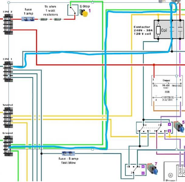
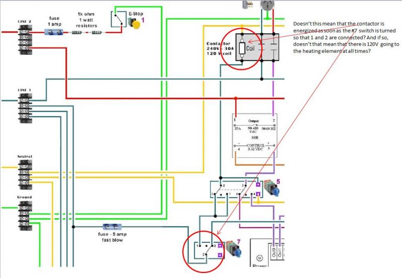
I'm really having a hard time getting my head around how this contactor thing works. I'm in the process of wiring up a system that will use 2 - 5500W heating elements with 2 pumps. It'll be HERMS based. In the picture below I can't see how the heating element wouldn't have 120V going through it at all times as long as switch 7 is on. This certainly wouldn't be good. Can someone take a look at this and let me know if I'm just going crazy here? Maybe explain how it's supposed to work?
contactor question.jpg
 
I see that, but what about sw 5. It looks to me that when sw 7 is in the other position it may be using the thermal to control it and the other position may be a manual over ride to turn the heater on manually. Since only part of the drawing is shown I can't tell.
 
I'm really having a hard time getting my head around how this contactor thing works. I'm in the process of wiring up a system that will use 2 - 5500W heating elements with 2 pumps. It'll be HERMS based. In the picture below I can't see how the heating element wouldn't have 120V going through it at all times as long as switch 7 is on. This certainly wouldn't be good. Can someone take a look at this and let me know if I'm just going crazy here? Maybe explain how it's supposed to work?
The heating element is a 240V element. It has one side of the 240V connected (blue wire) when the contactor is energized. The other side of the 240V is connected through the contactor and then through the SSR (red wire). The element will have power applied only when the SSR is allowing current flow. When the SSR is blocking current flow it is effectively disconnected. With only one side connected there is no path for current to flow.
 
The heating element is a 240V element. It has one side of the 240V connected (blue wire) when the contactor is energized. The other side of the 240V is connected through the contactor and then through the SSR (red wire). The element will have power applied only when the SSR is allowing current flow. When the SSR is blocking current flow it is effectively disconnected. With only one side connected there is no path for current to flow.

Hmmmm..... I'm still not getting it. Isn't the contactor energized at all times, meaning the blue is providing 1 leg of current to the heating element? And, when the SSR allows, the 2nd leg is providing current to the heating element? I guess I'm not seeing how the SSR is prohibiting current from reaching the element when it doesn't appear to be controlling the contactor.
 
Hmmmm..... I'm still not getting it. Isn't the contactor energized at all times, meaning the blue is providing 1 leg of current to the heating element? And, when the SSR allows, the 2nd leg is providing current to the heating element? I guess I'm not seeing how the SSR is prohibiting current from reaching the element when it doesn't appear to be controlling the contactor.
Ok... Question for you. What is the path for current to flow through the element when the SSR is set to not conduct current?
 
The SSR acts as a very fast digital light switch, controlled by the PID. The one leg that might always be on still won't power the element because the other leg is open.

Remember old christmas lights, where if one of the last bulbs went out, the entire string went out? There was still always power there, even to the first bulbs, but the entire circuit was open because one of the bulbs had burnt out. If you pulled out the neutral leg on a light bulb, and powered the hot leg, the light bulb wouldn't turn on. Circuit needs to be complete for any power to move.
 
This is what I'm envisioning the current of the blue (line 1) to be doing when #7 is switched to 1-2. Am I wrong?
You are showing a power path through the equipment ground connection at the element (green wire). There is no electrical path from the element shell to the power input terminals.
 
Heating elements only have two poles. The ground actually won't be wired to the element, but probably to either the rims tube, or the box you house your element into.

A random element:
http://www.bradfordwhitewaterheater...eating_element_water_heaters_41DUgx2B0-xL.jpg

If elements had 3 poles, your two hots and a neutral pole, that would be the case. I'm actually using 4 contactors in my two element build, so I can switch from 110 and 220 on each element (RIMS/BK). Only difference in mine is I'm switching the second legs on your diagram from Line 1 to Neutral. Still, the circuit wouldn't be complete unless the SSR is activated.
 
Sorry P-J for continuously talking over you. I'll step back. Best of luck Hefty on your build. I've got to go back to trying to seal my element to a tri-clamp fitting. As soon as pressure hits it it gives a slow leak.
 
You are showing a power path through the equipment ground connection at the element (green wire). There is no electrical path from the element shell to the power input terminals.

Agreed, there's no path there. Even if there was, that current path would trip your GFI.
 
Sorry P-J for continuously talking over you. I'll step back. Best of luck Hefty on your build. I've got to go back to trying to seal my element to a tri-clamp fitting. As soon as pressure hits it it gives a slow leak.
No sweat what so ever. You are doing just fine and it is appreciated.

Thanks.
 
You are showing a power path through the equipment ground connection at the element (green wire). There is no electrical path from the element shell to the power input terminals.

Ok, now I'm really confused. What would the current flow be if the SSR is allowing it to do so?
 
Nevermind.... I GET IT NOW!!! Whew!!! In a 240V circuit, the current doesn't flow back through the neutral, it flows back through the other leg. Therefore, when the SSR is not allowing the one leg to be active there is no path for the other leg to flow. When the SSR IS active, the current flows back and forth through the two legs.

So, P-J's schematic makes complete sense to me now! Back to building... :)
 
Back
Top