My simple two receptacle all grain build

Homebrew Talk - Beer, Wine, Mead, & Cider Brewing Discussion Forum

Help Support Homebrew Talk - Beer, Wine, Mead, & Cider Brewing Discussion Forum:

This site may earn a commission from merchant affiliate links, including eBay, Amazon, and others.

GC89

Well-Known Member
Joined
Jul 10, 2009
Messages
175
Reaction score
0
Location
Spokane/Pullman
Im making the jump to all grain so I thought I would share it all with you and hopefully gain some insight from those who have already been there.

At this stage things will be kept simple, mobile and storable. I am in college so this system needs to stay be able to be tucked away at my parents house and brought out on my brew weekends

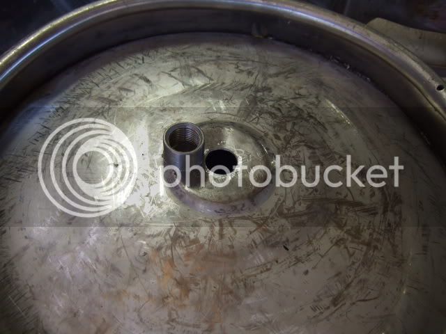
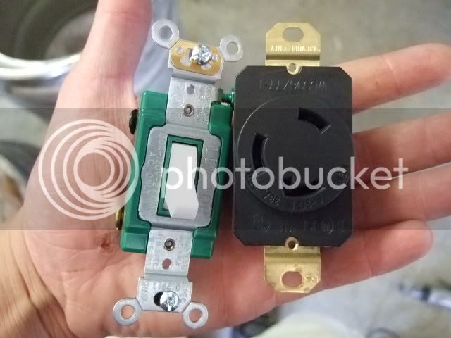
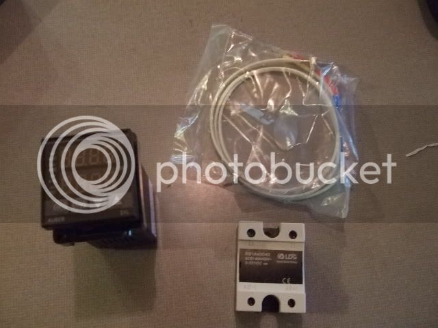
I am going with a two keggle system. The first will be the HLT using a 5500W ULD element and THIS PID (anyone have experience or imput on this pid?). The second keg will be the MLT which will be drained and sparged through back into the HLT which will then be used as a BK. I am planning on having both drain fittings located at the bottoms of the kegs. Still debating on going weldless or saving some money and welding fittings on. I have yet to see a weldless kit to install an element so that may make up my mind for me. If anyone has cheap sources for weldless or weld on stainless fittings, valves, ect I would appreciate it.

Pics up tomorrow
 
Are you planning to have the wort drain into a bucket from your MLT and then pour it into you HLT or are you planning to go no sparge?
 
If anyone has cheap sources for weldless or weld on stainless fittings, valves, ect I would appreciate it.

I did a lot of reasearch trying to find good prices for my build. The store 'KLG Stainless' on Ebay was generally the best for fittings. Check out my parts list here for specific parts/vendors.
 
If you have the ability to weld, by all means I would weld. l'm a cooler / kettle three vessel brewer but if I wanted to fit up some kegs i would consider silver solder. Search around, some are doing nice work this way.

fittings here:
Bargain Fittings
 
I have a 20 qt pot I was planning on draining my sparge water into that and then sparging through back into the hlt/bk but I also have a 10 gallon bucket so I may just empty into that. I have a nice mig here and even some stainless wire but its been a long time since I have welded stainless. I know kegs are spun so there thickness and consistency is not even which I figured would make welding with a mig tricky. Any experience with a mig on a keg? Its definitely cheaper to weld fittings in and less worry of leaks later on I am just concerned how they will turn out. So if I go ahead and weld I was thinking one of these cut in halve and welded on the bottom of each keg. Then the valves ect.
 
I wondered about that but figured a male would save space but female is definitely safer. The other thing I was debating is welding an elbow on the bottom so it turns then has the valve and then some 1/2 stainless tubing extending out past the rim and then down. I want to make it easy to convert to a stationary 2 or 3 tier system someday when I have the space.
 
pics as promised

Heres my jig to cut the tops of the kegs off.

101_0744.jpg

101_0746.jpg

101_0747.jpg

101_0748.jpg


I'm making a trip to my local good will and other thrift stores tomorrow in search of a 12'' lid
 
Finally found time to search for a lid. Couldnt find anything 12" or bigger at any of the thrift stores and finally stumbled on and 13" platter I guess it was. Anyways looked like it would work so I went home measured it out, set the jig and finally got my kegs cut.

DSCF1903.jpg
DSCF1904.jpg
DSCF1905.jpg
DSCF1906.jpg
DSCF1907.jpg
DSCF1909.jpg


I plan on making the one on the left and in the first pic showing the inside the MLT, and the right and second the HLT/BK. Went classic on the lid and used a 57 ford radio knob for the handle. Going to pick up a few more things tomorrow hopefully.
 
Finally got my controller parts from auber. Nothing too fancy just the PID, 3ft thermocouple and 40A SSR. Now I need a bit of help wiring it. Anyone have any good links showing diagrams using similar parts? I am having a tuff time finding any, thanks
 
Wiring is easy. There are (2) outputs +/- from the PID to the SSR. Then there is a LINE in to the SSR and LOAD out of the SSR. This is the voltage that will be switched.

That thermocouple is NOT water tight, the center pin is loose, it rotates, so you will have to seal that up.

That is about all I have to offer.
 
Thanks for the links, I figured it was pretty simple but I have heard lots of different things and the book I got with the PID is very difficult to understand. So I have heard of people powering the PID off of 120v and 220/240V and arguments for each that never really explain why or the benefits of either. Also since the SSR only has 4 pins and two are for the PID signals does it require 2 SSRs to run the element at 240?
 
Also since the SSR only has 4 pins and two are for the PID signals does it require 2 SSRs to run the element at 240?

Exactly! Look at it this way. The SSR is only a single pole, single throw switch that the PID turns on and off for you. The PID is not too difficult to use either. All you have to do is tell the PID what type of thermocouple you are using, set the temperature you want to achieve and let it autotune. Not so bad is it. You can customize the settings for a more complicated application but for most applications the autotune will work. The thermocouple I chose has a 1/2" NPT thread on it and is totally water tight. It was a tad expensive but was worth not having to worry about it.
 
Ok starting to make sense now. I went with a super simple Thermocouple that is water tight as I dont need anything fancy right now.

So Just to clarify

I Will pick up another 40A SSR to power the second leg to make 220/240 at the element.

Does the PID I purchased have the outputs to switch two SSRs or do I wire the outputs together. (again far from impressed with the booklet)

Does the PID Require 120 or 240 for its own power source? I have heard both.
 
Your PID sayes it has an input voltage of 90- 260VAC, sayes this on the Ebay page you linked.

Typically the PID only has (2) outputs, so to use them across 2 SSRs you will have to split the signal as such.

You dont HAVE to have (2) SSRs though, removing power from ONE of the 240 legs will kill the element. If you are worried about being able to turn off all voltage to the element, you can place the two hots on a DPST switch before they go to the element and SSR both. This way, regardless of what your PID may be commanding, YOU have conrol of the voltage to the element. Just a thought.


By the way, the thermocouple that you have posted, is notwater tight, I have the same one. I modified mine to make it water tight. Did you also buy a heat sink for the SSR?
 
Typically the PID only has (2) outputs, so to use them across 2 SSRs you will have to split the signal as such.

You dont HAVE to have (2) SSRs though, removing power from ONE of the 240 legs will kill the element.


Pol,

You have to be careful. Actually most PID's have only one output available to drive an SSR. You need to know if there is enough current drive available from the PID to drive two SSR's. The Auber Instruments PID's can supply 40 milliamps of drive current. Luckily the SSR's from Auber only require 12 milliamps of drive current to turn on. The Auber PID's can easily handle 24 milliamps of drive current needed for two SSR's. This may not be true with other manufacturers of PID's and SSR's.

I agree that breaking one of the hot legs on a 240 VAC circuit will kill the element. I think it would be safer though to break both legs because even though the element is off and one of the 240 legs are broken, there is live 120 VAC connected to the other side of the element.

Great suggestion on the heat sink! They will be switching a little bit of power and will get quite warm.
 
Pol,

You have to be careful. Actually most PID's have only one output available to drive an SSR. You need to know if there is enough current drive available from the PID to drive two SSR's. The Auber Instruments PID's can supply 40 milliamps of drive current. Luckily the SSR's from Auber only require 12 milliamps of drive current to turn on. The Auber PID's can easily handle 24 milliamps of drive current needed for two SSR's. This may not be true with other manufacturers of PID's and SSR's.

I agree that breaking one of the hot legs on a 240 VAC circuit will kill the element. I think it would be safer though to break both legs because even though the element is off and one of the 240 legs are broken, there is live 120 VAC connected to the other side of the element.


Which is exactly what the DPST switch is for.(you neglected to quote that very important part of my response) Because, I trust a real switch more than I do a PID that is running a program that I may or may not have configured properly. This is essentially a KILL switch, which IMHO, is needed on any electric system. The PID is for temp control, the switch is for ON/OFF

I fully understand that most PIDs have only one output for the SSR, this is why I stated that he would have to split the signal.

Also, he already posted all of the specs on this PID, it has a 40 mA signal... so therefore splitting the signal should work. 12mA is the MAX for most SSRs at MAX control voltage. Actually, through all of my building and searching I have never seen a 40A SSR with a MAX mA draw that is greater than 12mA. This being the MAX, most are rated at less than or equal to 12mA, since this is based on the control voltage which is generally variable between 4-32VDC. In his case, at 8VDC, he wont come close to that 12mA MAX on the SSR.

Now, there is a problem with the PID.
 
I actually went with auber on all my parts I figured its a little more but shipping would be faster and they are more reputable. I went with the SYL2352 Just a standard 40A SSR and This K type thermocouple. which is essentially the same, and your right I found it is not water tight. Did you put sealant on the back side or near the tip of the pin? Sorry I should have stated that I went with different equipment earlier. I have a few heat sinks around and am sure one of them will work. Any issues with too much heat even with a heat sink when confined to a box? I am wondering if I will end up needing lots of ventilation or even a small computer fan?

Appreciate all the help very much.


Okay, yah that is the same PID I use, that is fine then.

The thermocouple... I used some JB Putty on the backside of it. It is actually detailed in my Bling Bling HERMS thread, I will get you a link. This sealed it up and it works excellent now.

My heat sink is mounted OUTside my box, again that is shown in my build thread. The SSR is in the box, the heat sink is mounted to the SSR, but is OUTside the box.

My heat sink gets warm to the touch, not sure what would happen if it were inside the box.

Here is how I handled the thermocouple.
https://www.homebrewtalk.com/f11/bling-bling-electric-herms-conversion-93217/index6.html

Here is my heat sink mounting.
https://www.homebrewtalk.com/f11/bling-bling-electric-herms-conversion-93217/index12.html
 
I will either mount the heat sink outside the box or inside and have an old computer fan mounted to bring cool air in.

So here is the hole I drilled in the bottoms for the valve, welding store was closed so I couldn't get flux otherwise I would have welded them up today.
DSCF5622.jpg


Picked up a 30A 2pole switch today and had this plug laying around
DSCF5624.jpg


Heres the SSR, PID and Thermocouple.
DSCF5625.jpg
 
This project will have to wait until this weekend for more progress. Hoping to finish it up and run the first batch through it.

Though I would post my last project up, have a batch Im letting age for a week in the keg right now, then I will get to test it out.

DSCF5627.jpg


DSCF5628.jpg
 
Got the fittings welded up on the kegs, I had a leak I kept chasing on the one that will be the mlt. I also got the hole drilled for the element, a 10/3 cord with the right plug and all the cut outs in box that will house everything done. All I really have left is to wire everything and get the thermocouple ready. Anyone have a source for 10/12 splitter block? I'm having trouble finding one.
 
This looks like a really interesting thread, esp. since i wanna set up a very similar system.......too bad im so tired right now that none of it makes sense.
 
Very cool setup. Can't wait to see the finished product, although watching it being built is just as fun. Without flaring up a stupid ethics debate, where did you land the kegs? I have started to look around the area and haven't stumbled on anything yet, I need to step up my search efforts though.
 
I just put an ad on craigslist. One was $20 and the owner said it had been around since a party his son threw in 86:eek: 
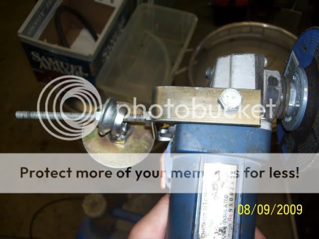
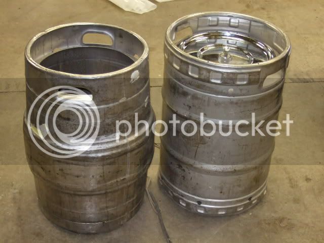
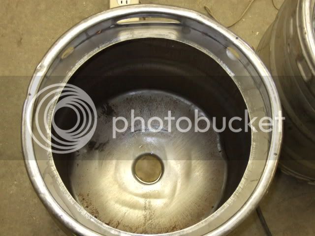
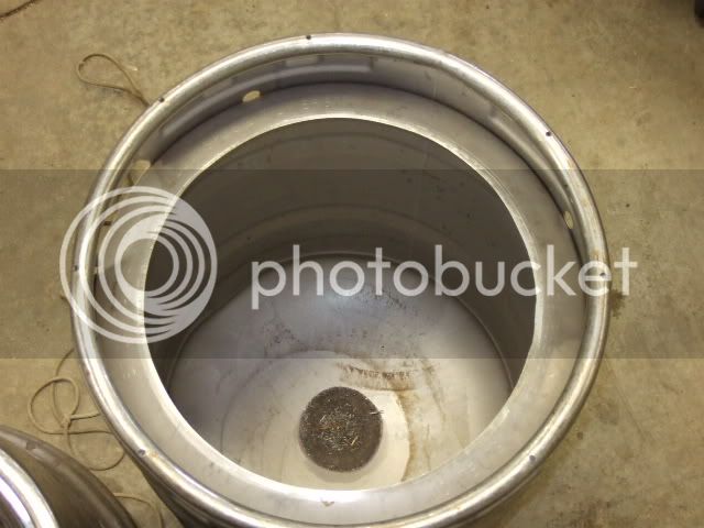
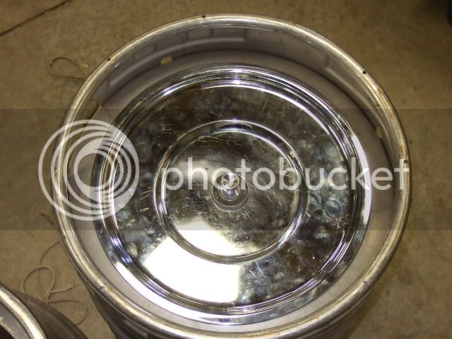
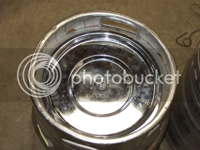
and I could still here a bit of sloshing in the bottom. I expected that to take a bit of cleaning but when I popped it it just smelled like vinegar and was spotless. The second one I found in a vacant house I was commissioned to clean out for the bank that was taking it over.

So I have all the wiring figured out except the power and ground for the PID, the manual isnt very clear. It shows 1,13,14 but doesn't specify what they are. Also it shows 9 & 10 as needing bridged?
 
Wiringdiagram.jpg


That is a copy of what I have so far for a wiring diagram. I am really hoping to wire this up and run a batch through it this weekend so I need all my wiring planned out ahead of time if I want to get everything done. If anyone can help me fill in any of the question marks I would appreciate it.
 
With as many people as there are using this PID someone has to be able to help me. Pol, I read through your build 3 times and have never seen anything pertaining to a wiring diagram. I really need to get this figured out by friday. Again here is the PID I am using and here is the manual for it. Maybe the manual will make more sense to someone else even if you dont have experience with this PID. All I need is to know if 9 & 10 need bridged for this application and how to power the PID
 
Easy answer.

Do not bridge 9 and 10, these are the + and - legs to power your PID. Send the - to one of them and the + to the other. Viola, you have power.
 
I am not an electrician, because of that, I am leary to give you advice. I hope you understand thats why I haven't answered your post sooner. I was hoping someone with more knowlege than I would chime in. Ok, with that being said, the first thing I would do is install a 220 Volt GFCI. I feel that is the most important thing to do first. I think that the switch that you have dead ended in your diagram is to switch power going to the PID. You need to connect the open end of your switch to terminal 9 of your PID and terminal 10 of your PID to ground. This allows you to power up or power down your PID by opening or closing the switch. I would also connect the ground to the rack you are using that holds all of your apparatus. You need to do this for safety sake. That's it I think. I hope someone with more knowlege chimes in but thats how I would do it. I hope that helps.
 
Since it appears that you have your power to your SSRs on switches, I would power the PID itself directly from the distribution block. This way, you can power down your element and leave the PID on for temp sensing, or setting parameters.

That is just my $.02

FWIW... my PID had no GROUND connection, it was + and -. Maybe Sawdustguy knows something I dont, but my PID had no ground wire connection.
 
Thanks guys exactly what I needed. The "example wiring" in the book threw me off. The other switch will be just for the PID that way I can have it on to check temps and turn it off without unplugging. I am using a GFCI breaker its already installed, and by ground I meant - so thats what I will connect to 10. Im an automotive guy so Im used to just saying hot or ground, which is a bit confusing in ac wiring I realize.

Thanks again guys pics up after this weekend and a report on how the system runs hopefully
 
Heres the updated wiring diagram, hopefully it will help someone else out who is looking for one. If you see anything else that needs changing let me know.

Wiringdiagram.jpg
 
Got everything wired up this weekend, and am already seeing thing to revise.

I kept the element leads accessible

DSCF5635.jpg


Element Installed

DSCF5639.jpg


Control Box

DSCF5638.jpg


And I found a stand, hence wanting to change a few things such as a plug on the end of the element leads like pols set up and where the thermocouple exits the box.

DSCF5636.jpg


and the drain from the HLT/BK - MLT

DSCF5641.jpg


I didnt get a chance to brew like I had hoped this weekend but I did fire it up for a test run with water. It brought 5 gal from 60 to a boil in about 20 min. Any Ideas on how to make this stand as efficient as it can be? I plan on adding a pump so I can transfer from the MLT back into the HLT/BK but how will that work with sparging? I am also thinking of installing a slide out platform for the mlt to sit on under. This way I could add the mash water, slide it out stir ect. Then when done fill a bucket with sparge water pump the first runnings up into the bk then sparge and Im on to boil.

Any thoughts???

I also harvested some of my hops this weekend, heres my throw together dryer

DSCF5631.jpg

DSCF5632.jpg


Some 1x4, stainless screen, a box and a small heater with a built in fan. I fired it up and took the temp. It will take it up to 101 and hold so it worked out perfect

Well that was my weekend
 
Need some help ASAP guys, Im having trouble setting the pid, how do I get to AT to change it for autotune, and also how do I change AM so I can use it in auto and manual mode? The instructions tell you what to do but not what buttons to push and by now I have pushed all of them in every order imaginable.
 
Ok so I never figured out how to change the settings I cant figure out how to change am to 0 or 1 so I have autotune or how to set it up to autotune. When I push set it will scroll through a bunch of settings but I dont see anything that says am or at, am I missing something?

On another note, I ran 2 batches in succession through the set up this weekend, I just ran it in auto mod and found that setting the temp between 192 and 198 gave me a nice slow boil. Things didnt go as smoothly as I hoped but the system worked and I nailed a 72 and 73% efficiency on my first 2 AG batches. A lot of the issues with the process were me figuring things out but there are a few changes I can make that will help a lot. Next weekend I will be cleaning up and painting the stand and getting fresh boards ect to make it cleaner and easier to make sure everything is sanitary. I added a plug to the element so I can dissconnect the bk from the control box easily. I might invest in a qdc thermocouple in the future too but for now its easy enough just to unscrew to clean. I was too busy to take pics this weekend. I only had friday to brew and pick the remainder of my hops (2nd batch was a wet ale) so I was busy in between temp checks, sparges and additions. Pics next weekend of the set up and changes.

A few things I need to work on are mlt efficiency. Had issues with dropping a good 2-3 degrees half way through Im going to give insulating it a shot first and possibly build a ring burner manifold to heat the edges of the bottom of it. Secondly has anyone figured out a good screen or filter for the bk?, had a bit of an issue with hops plugging the drain
 
Not busting your nuts here, but how is your element constructed?

You said that you left the leads accessible? Are they water tight? This is why I potted my connections. After a few boil overs I am glad that I did!

Just dont want you to die.
 
Its standard probably similar if not the same to yours. Im not too concerned at the moment because I only plan on doing 5 gal batches for the foreseeable future. If I were doing 10 gallon batches I would have to give beer away all the time to justify brewing as often as I like. Im not too concerned about boiling over. Also my element is on the far side from were I work with the system going and the keg has a separate ground and is gfci protected. I see how that could be an issue and didn't really think about the water tight factor so I might try to find some way to seal it up. Im glad I did it this way as I originally didn't have a plug on the end so it was hard wired to the box and I just changed the entire cord since I had like 4 of those laying around.

Pol do you think you could walk me through setting up the PID?
 
Back
Top