Need help with a simple wiring diagram please

Homebrew Talk - Beer, Wine, Mead, & Cider Brewing Discussion Forum

Help Support Homebrew Talk - Beer, Wine, Mead, & Cider Brewing Discussion Forum:

This site may earn a commission from merchant affiliate links, including eBay, Amazon, and others.

Sublime8365

Well-Known Member
Joined
Jan 31, 2011
Messages
149
Reaction score
1
Location
Houston
I'm building a simple HERMS system and could use some help on wiring up my PID/SSR/element.

The plan is to pump the wort from my cooler/MT through what was previously an immersion chiller that will be placed in my HLT that has a 2000w heating element (I don't have a 240v power source so 120v/20A is what I'm going with).

I am not planning to use any switches or control the pump through this diagram unless someone makes the case for doing so. So the pump will be plugged in and powered separately and will run continously throughout the mash.

I have:
2000w heating element
Auber SYL-2352 PID
40A/250V SSR-40 DA with heat sink
K-type thermocouple (I know I can use an RTD but I already had the k-type and thought I'd try to make it work)

Since I'm using a 120v power source I was going to plug the system into a surge protector and just use the switch on that to turn the power on/off at the beginning/end of the mash.

Can someone help me out here?
 
This is my first stab at a diagram (based on a P-J diagram that I crudely modified). Any reason this wouldn't work?


thumb2_wiring-diagram-56797.png
 
Diagram looks OK if you really wanna keep it that simple. I would suggest a switch to control a contactor after the SSR. I suggest that for 2 reasons.

1 safety of having a contactor that fails in the off position. Your current setup the only way to turn the element off is to unplug the whole control box.

2. Its nice to be able to have your pid on without having power to the element. Its just a convenience thing but its much easier to avoid dry firing your element this way.
 
So I'm looking to implement that switch you were talking about. The switch goes between the SSR and the heating element on that diagram? Not between the power source and the SSR?

Looking to just use a simple light switch. Is that all I need?
 
The switch goes to a contractor that is between the SSR and element. There are switches rated at 30A but a contractor keeps all the high amperage stuff further from your hands.
 
It appears from your drawing that you're going to supply the PID with power from another source. Why? It draws very little amperage and complicates your design.

Regarding the pump, is it a March or Chugger (magnetically connected impeller) do you at least have a ball valve on there to control flow? Otherwise the propensity to have stuck mashes goes up considerably.
 
Yeah I'll end up not powering the PID seperately.

Do you have enough knowledge about circuitry to comment on my wiring diagram above? PJ seemed to indicate it's a mess and judging by what I've read on here he seems to be the resident expert.
 
Yeah I'll end up not powering the PID seperately.

Do you have enough knowledge about circuitry to comment on my wiring diagram above? PJ seemed to indicate it's a mess and judging by what I've read on here he seems to be the resident expert.
WRONG.!

You did a good job.

(Sorry about the diversion for you.)
 
Awesome! Just took a lot of searching through the forums for me to get what I needed (and a few home brews to allow me to be patient enough :mug:

So that contactor that I linked to is good?
 
The contactor is A-Ok. It is a good choice.

The suggestion to power the PID from the same outlet is valid. I would also suggest doing that. The PID draws less than an amp of current. No problem.
 
Sweet, thanks.

Two more questions for the crowd:

I'm planning on converting a (plastic) toolbox into my control panel.

1) Should I look to keep my heat sink on the outside of the toolbox (searching for the forums from similar builds I saw people putting it on the outside but don't know if a 2000w element would produce less heat than a larger watt element)

2) If I don't really want to drill holes in the bottom of the toolbox to mount my parts, could I just use a piece of wood that's formed to the shape of the bottom of the toolbox or should I use some sort of metal?
 
I would suggest mounting the heat sink on the outside of the controller. This way the heat is dissipated to the room instead of being contained & effecting everything else.

Mounting the components to a thin piece of plywood is Ok. No problem. Most all of the components used in your build do not have any ground bonding to its mount.

Go for it.

Hope this makes sense and is of some help.

P-J
 
Ok I lied when I said last question before :D

For the power going to the element, can that be grounded to the nut on the element itself or does that need to be grounded to the kettle?
 
So just thinking through mounting my heat sink on the outside of the tool box.

I'm trying to figure out the easiest way to do this. I'm going with the tool box solution because (among being cheap) it's easy to just close it up and put it back into storage. So if I'm going to have the heat sink on the outside of the box, I want it to be easy to put right back into the box when finished.

Ideas I've had so far:

1) Mount the heat sink to the inside lid of the box. I would be ok with a more permanent mounting here as long as I have the room to just close the box back up easily with the sink mounted.

2) Mount is somewhere to the side. Problem here is I want a way that I can easily just grab the heat sink from where it's mounted and put it back into the box. I don't really feel like screwing and unscrewing it every use. It wouldn't be the end of the world though.

3) Just don't mount it. I could just have it that I just take it out of the toolbox and place the sink next to the toolbox when I'm using it.

Anyone have any input? Leaning towards 1 right now.

Find a way to mount it an keep it there. Moving parts around is likely to lead to loose connections, a wire getting snagged on something or some sort of failure.
 
The heat sink has the SSR(s) attached to the back, the SSR(s) have power lines and signaling lines running to them. Trying to move the heatsink around means moving all of this. Not a good idea.
 
OK so I got everything wired up and finally got around to testing it the past few nights. Hasn't been working 100%. When I power everything up, the PID display is fine and I seem to be getting accurate (or at least close enough for now) readings on the temp. The element turns on. The heat exchange seems to work fine.

2 things aren't working though:
The switch is not turning the element on/off. It's on regardless of what position the switch is at.
The PID is not controlling the element. Is stays on all the time. My water heats up to where my set temp is and just keeps on heating.

Any ideas as to why this would be? I'm pretty confident I wired it to the "specs" of the diagram I posted. Are there any "common" mistakes that would cause this that I could check?

Thanks in advance.
 
Post photos of your PID, SSR, Contactor, element selection switch, and recepticals. Otherwise it's a guessing game.
 
Post photos of your PID, SSR, Contactor, element selection switch, and recepticals. Otherwise it's a guessing game.

Ok I'll post pics as soon as I can. Reading through the forums a bit it's possible that I have a faulty SSR I guess.

How would I test that with a voltmeter?

Would that affect my contactor not working with my switch?
 
Subscribed.

I like the simplicity of your design. I'm going for something similar. Can you post some more pics just to see what you got going on. Was this all pretty easy to wire up? I'm just learning about this kind of stuff now but have a pretty good idea of what to do but was just wondering what you thought.
 
Reading through the forums a bit it's possible that I have a faulty SSR I guess. How would I test that with a voltmeter?

Your PID should put out a small DC current, around 12VDC. Using your multimeter in DC mode, disconnect the SSR feed from the PID and set it to manual at 100% - check the voltage across the two posts; if you have 12VDC, good. Turn everything off, reconnect the SSR to the PID, and disconnect the main feed in / out of the SSR (the 120v line). With your meter set to measure ohms, check across the two posts - you should get little or no reading. Then turn on the PID, set to 100%, and measure again - you should measure a much higher reading, indicating that the switch has closed and you have a clear path for current. How your multimeter is set up may change how your output looks, depending on whether you have a digital or analog device. If all that has worked so far, plug it all back in as normal, and take voltage readings (AC) from the power-in post on the SSR (touch one lead to the post, another to your neutral hub (120v) or the other hot line (240v), doesn't matter). Then do the same for the power-out post. Both should read the same with the PID at 100% manual.

This should, hopefully, get you to where we can figure out what's wrong.

Would that affect my contactor not working with my switch?

Your contactor has nothing to do with your SSR. The ability for the contactor to open / close is totally independant of what the SSR is doing. If your contactor is not closing the circuit correctly, then you have a problem there and no amount of trouble shooting the SSR will fix it.

-Kevin
 
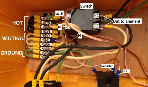
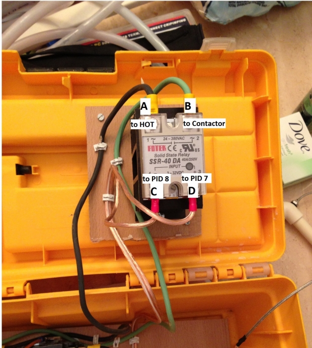
Ok here it is. Sorry in advance if it looks sloppy (it is), I'm a novice at this stuff. Also, I know I have a green wire for hot in one instance. sorry for the confusion.

Hope you can follow (look at both pics to understand the labeling)

thumb2_photo-dec-10-5-53-47-pm-57601.jpg

thumb2_photo-dec-10-5-53-54-pm-57602.jpg


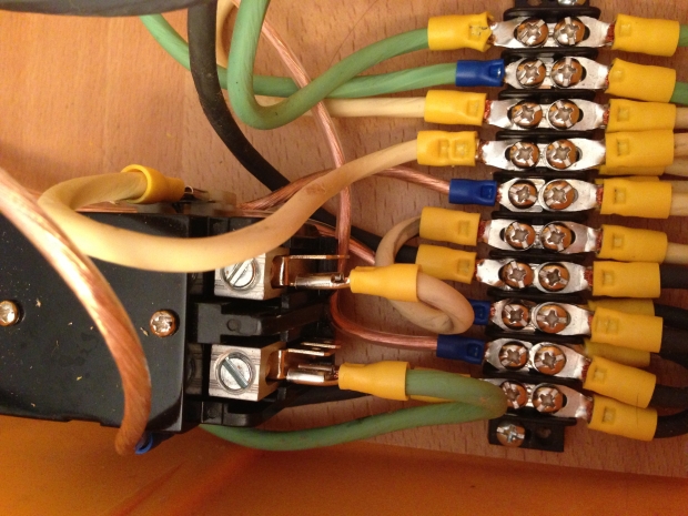
More pics of contactor:
thumb2_photo-dec-10-5-54-08-pm-57603.jpg

thumb2_photo-dec-10-5-54-17-pm-57604.jpg
 
are you feeding your element with a regular wall receptacle mounted in the side of your toolbox / enclousure? If so there should only be one set a wires going to it.
 
So last week I made the fix that I thought would solve this once and for all and it didn't. :mad:

Those 2 sets of wires going to it were 1) for the power input from my wall outlet, and 2) the outlet to the heating element.

Obviously that doesn't work on the same outlet so I installed another and now my element goes out one and the wall outlet goes in the other.

Problem is that now the element won't turn on at all (regardless of the way the switch is flipped). So before it wouldn't turn off, now it won't turn on.

When I flip the switch I can hear the contactor switching on/off but the element won't go on. Any ideas?
 
A bit of advice - you made a drawing and the folks who looked at it said it was ok. Now when you build your panel you need to stick to the drawing. Don't make modifications on the fly. There could be unintended consequences.

Please post a pic of the outside of the box with some text about it. That might help.
 
I've studied your pictures a few times now and for the life of me can't tell what's going on in there... Sorry, but I'll be of no help on this one.

BTW - is that speaker wire you're running?
 
A bit of advice - you made a drawing and the folks who looked at it said it was ok. Now when you build your panel you need to stick to the drawing. Don't make modifications on the fly. There could be unintended consequences.

Please post a pic of the outside of the box with some text about it. That might help.

I didn't try to make any change, I just made a stupid mistake. How I have it setup now is to the 'specs' of the diagram I believe (with the exception of the PID drawing power from the same source as the element.

I'll post pics sometime next week when I'm home from the holidays.

Thanks.
 
I've studied your pictures a few times now and for the life of me can't tell what's going on in there... Sorry, but I'll be of no help on this one.

BTW - is that speaker wire you're running?

I'll try to take some better pics at some point.

Yes I have some speaker wire in there where there's lower voltage (to the PID, etc).
 
In your picture it looks like speaker wire is labeled HOT and CONTACTOR... I don't think the insulation on speaker wire is rated for much...
 
Speaker wire is ok for low voltage like the 12v signal from pid to ssr. It is not ok for 110v like you have it connected. Pick up some alarm or sprinkler wire a hd or lowes rated for 250v for pid power, contactor coil and other low current high voltage signals.

Your design is pretty basic and you should be able to ohm out all connections with a multimeter.

Consider bypassing the ssr and pid and verify you can turn the element on/off with a switch controlling the contactor coil.
If this works then hook up the pid and ssr and test in manual mode.
If this works then program the pod and test in auto mode.
 
For the original setup did you break the tabs on the outlet? If not the heater was getting power directly from the incoming source through the outlet. That shouldn't matter now that you are using two outlets, but I figured I mention it.

I'm not familiar with the contactor, but in the schematic it is shown as if the contacts close across the distance of the relay, and that is how it appears to be wired. Some contactors close and connect the adjacent terminals, so that one set is on one side, the other set on the opposite side. Was there a diagram with it when you bought it? Or anyone already familiar with this contactor? Just one thought. Do you have updated pictures to show the new outlets?
 

Latest posts

Back
Top