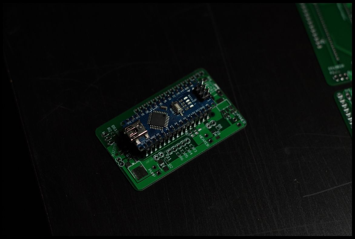
OK thank you very much! So now its clear for me, most of them is just as precautions and for better working but without will still work, like hooked on the image which I showed. I will probably skip capacitors and I am planning to use internal voltage regulator from arduino Uno. Can you just explain me one more thing? In your PCB and schemo Heater, Buzz etc is connected directly to VIN (~12V) and then through some stuff (mosfet or transistors and resistors) to pins. On the pic without it its other way around, directly to ground and then to pins.
On the DanielXian board the schemo is like directly to GND and to pins where on the board its like on your board, +12 and then through transistors to pins (imgs attached). So it doesnt matter which way do you connect it? Or there is a mistake? I do not want to fry any of the element
")
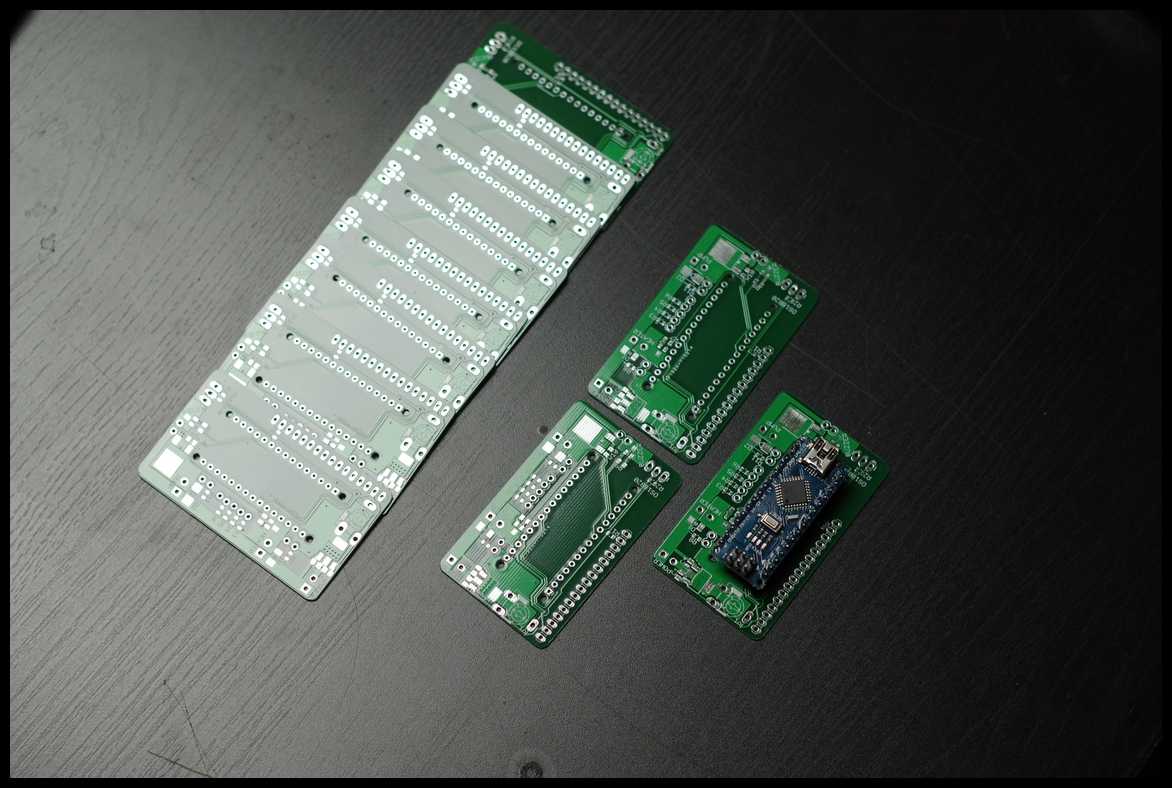
Hopefully everything will fit to the prototype board.
One more question here, do I have to use soldermask etc if using prototype board and just solder to make lines?