My 60 amp Kal mutation

Homebrew Talk - Beer, Wine, Mead, & Cider Brewing Discussion Forum

Help Support Homebrew Talk - Beer, Wine, Mead, & Cider Brewing Discussion Forum:

This site may earn a commission from merchant affiliate links, including eBay, Amazon, and others.

theichthus

Well-Known Member
Joined
Jan 8, 2010
Messages
58
Reaction score
1
Location
Columbus, OH
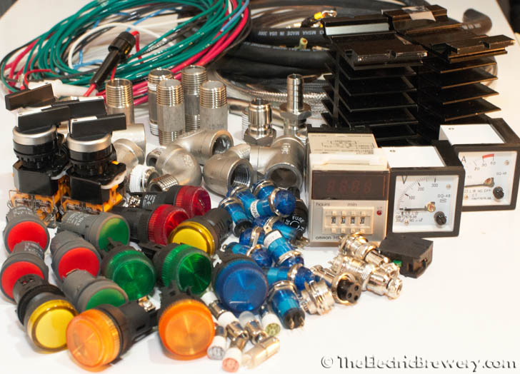
I finally have made all of the large purchases for my Kal mutation and will document progress here as well as ask for lots of help.

My rig differs in that I am building a panel capable of firing two 5500W elements simultaneously. Minor differences are that all my relay coils and my pumps are 240V so my wiring will differ significantly.

The last change is that I am hoping to use the pictured 6500W thyristor from ebay to control my Boil Kettle. In trying to trim expenses where I could, the thermocouple and PID seemed unnecessary. Plus I wanted something to be unique.

I am confused that is has 4 terminals. Do you think i run both legs throught it? I unsoldered the potentiometer, because I didn't have room to mount the whole unit to the door of the panel.

Has anyone used one of these? Can anyone offer advice? Thanks. I also included my planned component placement for the heck of it. Happy for advice there too. Thanks!

thy1-1500.jpg


thy 2-1500.jpg


photo 1-1500.jpg


photo 2-1500.jpg
 
I have one of these units. A 6500W rated one for a 4500W element.

Yes you run both hot legs into/out of the unit.

THANK YOU! Can you be more specific just to make sure I don't screw anything up? I am assuming the hot legs go IN to the "L" terminals and come out the "N" terminals?

Thanks again SO much. Do you see any problems with me moving the pot somewhere else and just running leads from it to the PCB?
 
I'm guessing you go in on one side and out the other. L and N signify the wire (Hot A / Hot B) and the writing above would tell you which side is line and which side is load. I can't read whatever language that's written in though...
 
I'm guessing you go in on one side and out the other. L and N signify the wire (Hot A / Hot B) and the writing above would tell you which side is line and which side is load. I can't read whatever language that's written in though...

Nice buil BTW. I just spent sometime enjoying your work. So, after a little thought and observation, I think only 1 leg needs to go through the unit. Check my thinking. In the underside of the PCB, the two "N" terminals are connected by a line of solder. The underside does show the terminals connecting to something else, but nothing is there... So it looks like whatever is connected to the N terminals might as well just skip the board.... See photos. I am reading PCB correctly?

photo 1.jpg


photo 2.jpg
 
Definitely looks like solid logic there. Not sure which side would be Line or Load, but I have to agree that N appears to be a simple through-put line and could be skipped given that it doesn't seem to connect to anything else.
 
I am stumped. I purchases my 120V LED lights before I had my whole panel planned out. I should have purchased 240V LEDS--hindsight is 20/20.

I have a switch controling my boil kettle element through a relay that has a 240V coil. I would like my 120V LED to be a simple indicator. I believe the set up below should work, but my question is represented in green. Can electricity feed through the coil and turn my light on at all times?

I know that using a double pole switch could take care of my problem, but I would like as few wires running from the back plate to the door as possible. My pumps (also 240) use a double pole switch because without it there would be live electric outside the panel even when the switch off. Since the coil is internal I don't feel that level of safety is necessary.

Bottom line is this: Will this work?:confused:

Diagram.jpg
 
My guess is that you should be fine. Unless the coil is dual-rated at 120/240v. Then again, if the LEDs are relatively low draw (which they likely are) it's entirely possible that you'll get enough voltage through the coil and over to neutral to light up the LED.

How much would it cost to return the 120v LEDs and get 240V LEDs? Then your problems would be solved.
 
Click. Buzz. Pop. And there was smoke.

It was easy to find my problem. Please learn from my mistake. When witing power I ran out of red 18 AWG, so I thought for the last little leg it won't hurt if I use the white wire..... Maybe if I had wired the entire panel in one day (would that even be possible?) Anyway, a day or two later, I think to myself , "Where can I tie in this neutral wire?" Oh! Look at that white wire! I will tie right into that.

Now I just have to pray that it did not fry any of my small electronics...

Lesson learned: Color code your wires and if you run out of a color, STOP and go get some.

What really stinks is that I left all of my tools at work so if I want to fix it this weekend I have to go to the office first. :/

:mad:

image-159985854.jpg


image-439552476.jpg


image-2202203524.jpg
 
After a little more thought
Lesson 2: I should have installed the 8 amp in-line fuse that I purchased... I need to find that... That would have at least allowed me to reuse some of the wire and could have prevented some damage.
 
Well thank God. It works and there is no obvious damage from my earlier mistakes. There are a few kinks but nothing big. A few LEDs are screwy and I need a double pole switch on the BK relay to keep that indicator light from always being on but it seems to work! Now to work on the kettles. And the bench. And the exhaust fan. And the pumps. Then the lagering fridge. Then the keezer. Then the yeast lab..... Sheesh.

image-1524987790.jpg
 
Wow! How the heck did you fry the wires so bad before tripping the 60A? breaker? Did it even trip? I noticed you did not install internal breakers as others have done. An inline fuse would help, but just make sure that your wiring is the correct gauge for 5500W elements, or the melty part might happen again. . . Also GFIC is a must have for safety. Better to be safe than badly burned or worse. Good luck!
 
Nice job - I like the funky mix of old with new: Old school analog dial(s) with newer LED segmented displays.

I thought about doing my volt/amp meter as analog ones as well and even bought a couple but in the end decided to all LED segmented displays for everything. The two meters now sit in my junk pile: ;)

IMG_7804.jpg


(They're at the right side of the image)

@PLOVE: He probably created a short by accident and pulled 60A through the smaller 18ga wire, causing them to overheat/fry before the breaker popped.

Kal
 
Thanks for the attention everyone! I need to post a few new photos, but let me answer a few questions.

1. @BadNewsBrewery: Yes. It is run through a 60 amp GFI in my panel.
2. @PLOVE: 60 amps was run through the 18 AWG wire due to the short. That did end up tripping the breaker.
3. @Mun: Ajgeo is correct. It is the Auber SYL-1512A
4. @kal: I really wanted to make my panel as original as possible, but I could seriously not think of ANY way to improve on your design without going overboard (Extreme Automation). Props for thinking of everything. So, I tried to make something as functional but unique. I almost didn't have a mash PID because it seemed overkill to use it only for a temperature probe. I used they thyristor for the boil kettle because it theoretically gives me infinite setting. I did realize before I even started it up though that the ammeter is pointless as the thyristor regulates voltage. So I bought a voltmeter from the same company. I installed it with excitement to find out I order the DC model and not the AC. Grrr. 3 more weeks from China to get the 3rd and final meter! P.S. Committed to buying you some beer when I finally brew my first batch on the system. Thanks for everything.

General update: Control panel works as best as I can tell. Progress is delayed as my brewery build is tied to a greater project in my garage. The 16 feet of wall where the brewery belongs is taken up by enough insulation and sheeting to finally insulate my roof so I can brew comfortably in my detached garage yer round. Easy to find the time to tinker with the brewery. Hard to find the time to insulate a garage roof on 90 degree days.
 
My guess is that you should be fine. Unless the coil is dual-rated at 120/240v. Then again, if the LEDs are relatively low draw (which they likely are) it's entirely possible that you'll get enough voltage through the coil and over to neutral to light up the LED.

How much would it cost to return the 120v LEDs and get 240V LEDs? Then your problems would be solved.

In case anyone is asking the same question I should declare that this did not work. That light shone bright. I ended up ordering new 240V LEDs. It was not as expensive as I thought. $14 after shipping.
 
I almost didn't have a mash PID because it seemed overkill to use it only for a temperature probe.
I thought it would be somewhat useless too but it's turned out to be more useful than I thought. The mash temp always lags behind the HLT temp that you used to control the mash temp, so knowing the mash temp shows you how fast (or slow) it follows. Without this I wouldn't know (say) when the entire mash has made it up to 168F mashout temp. I can't even stick a thermometer in the top of the mash to check since that's only the top. it takes time for the heat to work its way down through the entire mash.

I did a step mash on my last brew too where I wanted to hold at specific temps for specific times and knowing the exact mash temp lets me do this and not guess.

Kal
 
I bought this stainless coil, and these fittings. The nut BARELY fits over the tubing. I forced it on and off once and left the coil kind of banged up. Attached is a photo of the damage after spending 10 minutes on it with emory cloth.

1. Will those scars in the tubing prevent me from getting a good seal?

2. What should I do?

Strangely, other pieces of the compression fitting fit over the tube just fine. But the nut on both fittings will not fit well over either end of the coil. Can I ream out the nut with a file? Thanks everyone.

ss TUBE.jpg
 
What did you use for a plug and receptacle for the main power? I'm doing a 60A panel and ended up buying pin and sleeve connectors


Sent from my iPhone using Home Brew
 
I found a plug receptacle combo on eBay for 1/3 the price of new. The only caveat was that the plug configuration is technically 60 amp 3 phase. But rather than three phases I am using it for H-H-N. Neither of these photos are very good--but here they are. ImageUploadedByHome Brew1414861930.637531.jpgImageUploadedByHome Brew1414861947.893641.jpg

I am trying to imagine your set up. Is your sleeve hardwired into a box or something?
 
Not yet still working on building the panel. I plan on having it come out of a spa panel with a cable gland and some 6-4 SO and have the sleeve with about 12ft of cord on it. Other side on the panel same idea but only 1-2ft of cord off it.


Sent from my iPhone using Home Brew
 
I used a 3 phase setup so I could keep the gfi functional in a spa panel mounted away from the control panel. That way if it trips it's a good ways away.


Sent from my iPhone using Home Brew
 
Back
Top