TeensyPi Networked Temperature Controller

Homebrew Talk - Beer, Wine, Mead, & Cider Brewing Discussion Forum

Help Support Homebrew Talk - Beer, Wine, Mead, & Cider Brewing Discussion Forum:

This site may earn a commission from merchant affiliate links, including eBay, Amazon, and others.
Any thought of using that blank area for a bus to connect temp sensors and another for switches?

The DATA, 3V3 and GND connectors are all you need for the sensors and add the 5V connector for switches. The blanks area is very close to the RJ-45 and USB connectors, which are metal, so I chose to avoid them altogether.

Making a bus for the switches and temp sensors tends to configure them as a "star" network, which the app notes say you should avoid if possible, due to refection problems.
 
Also, did you ever figure out the LCD's? I got the Raspberry Pi LCD Plate from Adafruit (i2c and buttons) and cannot seem to get it to work. I'm not sure if it is because of a conflict with the Teensy... I am currently troubleshooting.

If you're using my latest .img file for the RPi, the I2C interface should already be baked in.

I've got 8 4x20 LCD's running on the RPi I2C bus right now using another board I created. :ban:

I'm using python code ( ugh :cross: ) right now to run them, and I'm looking for a "C" library for the RPi, to make it a little easier to integrate with the php. So far no luck, but the wiringPi library looks promising.
 
What's odd, when I run the adafruit test script for the i2c LCD plate, it registers the buttons when I push them, but no characters show up on the screen. The backlight lights but nothing else. I've checked my connections over and over and resoldered some. Going to give it a rest tonight and check again tomorrow.
 
What's odd, when I run the adafruit test script for the i2c LCD plate, it registers the buttons when I push them, but no characters show up on the screen. The backlight lights but nothing else. I've checked my connections over and over and resoldered some. Going to give it a rest tonight and check again tomorrow.

Is the backlight blanking out the characters?
 
Anyone else had issues with ActionDataWithMySQL.php not assigning the chip name correctly to an action? The temp value is correct but the name isn't. The chip names are all correct in the database and they are available in the dropdown.
 
I know my blue and white Adafruit LCD will get bright enough to mask the characters, I just put a 10K pot across the pins to change the contrast. I don't have it connected to my Teensy, I'm using it on my BrewTroller.
 
I would be interested in a board if somebody wanted to set up the group buy.

Jimmay--nicely done. This is glorious work. Excited to get my hardware.
 
Thanks for the help, didn't think of turning the pot to the left :drunk:! Helibrewer was correct, the backlight was too bright... so it was working all along :smack:. Also the RGB code was causing the screen to go out, and using the LCD.RED fixed that.
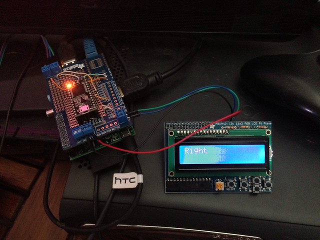
8576562541_dd3659ec23_z.jpg


Once I get some free time I am going to update my UI files to reflect the new PID stuff and will make that available.

I would also be interested in a board if people are doing a group buy.

@jimmayhugh are you still tweaking your board layout?
 
Anyone else had issues with ActionDataWithMySQL.php not assigning the chip name correctly to an action? The temp value is correct but the name isn't. The chip names are all correct in the database and they are available in the dropdown.

You can put "echo" commands to output the results of the database queries to the webpage to see if the problem lies with the query result, that may help to figure out the problem.
 
I'm using python code ( ugh :cross: ) right now to run them, and I'm looking for a "C" library for the RPi, to make it a little easier to integrate with the php. So far no luck, but the wiringPi library looks promising.

Do you have the python code on your GitHub?
 
Do you have the python code on your GitHub?

No, I'm using the Adafruit library and this test code:
Code:
#!/usr/bin/python

from time import sleep
from Adafruit_I2C import Adafruit_I2C
from Adafruit_MCP230xx import Adafruit_MCP230XX
from Adafruit_CharLCDPlate import Adafruit_CharLCDPlate

import smbus
import socket,os
import StringIO
import csv
import socket
import MySQLdb as mdb
import sys


# connect to the database
con = None
lcdinfo = []
tpID = 0
tpTempAddr = 1
tpTcAddr = 2
tpThAddr = 3
tpLCD = 4
tpRGB = 5

try:
    con = mdb.connect('localhost', 'teensypi', 'teensypi', 'teensypi')
    cur = con.cursor()
    cur2 = con.cursor()
    cur.execute("SELECT id, tempAddr, tcAddr, thAddr, lcd, rgb FROM action WHERE lcd>0")
    numrows = int(cur.rowcount)
#    rows = cur.fetchall()
#    print numrows
    for x in range(0, numrows):
        row = cur.fetchone()
        lcdinfo.append([])
#        print row
        lcdinfo[x].append(row[tpID])
#        print lcdinfo[x][0]
        cur2.execute("SELECT name FROM chipNames where address = %s",(row[1]))
        lcdinfo[x].append(cur2.fetchone())
#        print lcdinfo[x][1][0]
#        print lcdinfo[x][1][0].center(20, ' ')
        cur2.execute("SELECT name FROM chipNames where address = %s",(row[2]))
        lcdinfo[x].append(cur2.fetchone())
#        print lcdinfo[x][2]
        cur2.execute("SELECT name FROM chipNames where address = %s",(row[3]))
        lcdinfo[x].append(cur2.fetchone())
#        print lcdinfo[x][3]
        lcdinfo[x].append(int(row[tpLCD]))
#        print lcdinfo[x][4]
        lcdinfo[x].append(int(row[tpRGB]))
#        print lcdinfo[x][tpRGB]
        
except mdb.Error, e:
  
    print "Error %d: %s" % (e.args[0], e.args[1])
    sys.exit(1)

finally:
    
    if con:
        con.close()

# initialize the LCD plate(s)
# use busnum = 0 for raspi version 1 (256MB) and busnum = 1 for version 2

lcd = []

for x in range(0,numrows):
    lcd.append([])
    lcd[x] = Adafruit_CharLCDPlate(busnum = 0, address=(lcdinfo[x][4]))
    lcd[x].begin(20, 4)
# clear display
    lcd[x].clear()
    lcd[x].setCursor(0, 0)
    lcd[x].message(((lcdinfo[x][tpTempAddr])[0])[0:20].center(20, ' '))
    lcd[x].setCursor(0,1)
    lcd[x].message("Temperature: ")
    lcd[x].setCursor(0,2)
    lcd[x].message((lcdinfo[x][tpTcAddr])[0])
    lcd[x].message(": ")
    lcd[x].setCursor(0,3)
    lcd[x].message((lcdinfo[x][tpThAddr])[0])
    lcd[x].message(": ")
# first loop, just changes the color
while 1:
#    sleep(.5)
    s = socket.socket(socket.AF_UNIX, socket.SOCK_STREAM)
    s.connect("/tmp/teensypi")
    s.send('C\n')
    data = s.recv(1024)
    s.close()

    for x in range(0,numrows):
        splitActionArray = data.split(';', lcdinfo[x][0])
        actionItem = splitActionArray[lcdinfo[x][tpID]]
#        print actionItem
        splitActionItem = actionItem.split(',')
        lcd[x].setCursor(17,1)
        lcd[x].message(splitActionItem[1])
        lcd[x].setCursor(16,2)
        if lcdinfo[x][tpRGB] == 0:
          lcd[x].backlight(lcd[x].RED)          
        if splitActionItem[2] == 'F':
          lcd[x].message(" OFF")
        else:
          lcd[x].message(" ON ")
          if lcdinfo[x][tpRGB] == 1:
            lcd[x].backlight(lcd[x].BLUE)
        lcd[x].setCursor(16,3)     
        if splitActionItem[3] == 'F':
          lcd[x].message(" OFF")
        else:
          lcd[x].message(" ON ")
          if lcdinfo[x][tpRGB] == 1:
              lcd[x].backlight(lcd[x].RED)
        if splitActionItem[2] == 'F' and splitActionItem[3] == 'F' and lcdinfo[x][tpRGB] == 1:
          lcd[x].backlight(lcd[x].GREEN)
 
No, I'm using the Adafruit library and this test code:
Code:
#!/usr/bin/python

from time import sleep
from Adafruit_I2C import Adafruit_I2C
from Adafruit_MCP230xx import Adafruit_MCP230XX
from Adafruit_CharLCDPlate import Adafruit_CharLCDPlate

import smbus
import socket,os
import StringIO
import csv
import socket
import MySQLdb as mdb
import sys

did you need to install new python libraries?
 
In case anyone missed it, Teensyduino 1.13 has been released.


Teensyduino 1.13 has been released.

http://www.pjrc.com/teensy/td_download.html

For use without Arduino, see the sample makefile in hardware/teensy/cores/teensy3 after installing.

These are the changes since Teensyduino 1.12:


Support for Arduino 1.0.4
Fix Serial.write(0)
Turkish keyboard layout (Teensy 3.0)
Fix while(!Serial)
Fixes for ST7565 library (Teensy 3.0)
Add OctoWS2811 library
Update libraries: Keypad, Metro, OneWire, Ping, ST7565
 
I'm making some headway in getting the LCDs to work with the RPi :rockin:

Not interested in causing a flame war of C,C++ vs. Python, I just don't want to have to learn another language. :p

I'm using the wiringPi Library as the basis for the code, and the board I'm currently using is my own version of the Adafruit RGB LCD Pi Plate.

I'm also using 4x20 LCDs, and am not yet implementing the extra switches. If you want to play along, follow the download and install instuctions, and then get this code:
Code:
#include <stdio.h>
#include <stdlib.h>
#include <stdint.h>
#include <errno.h>

#include <wiringPi.h>
#include <lcd.h>

// MCP23S17 Registers

#define IOCON           0x0A

#define IODIRA          0x00
#define IPOLA           0x02
#define GPINTENA        0x04
#define DEFVALA         0x06
#define INTCONA         0x08
#define GPPUA           0x0C
#define INTFA           0x0E
#define INTCAPA         0x10
#define GPIOA           0x12
#define OLATA           0x14

#define IODIRB          0x01
#define IPOLB           0x03
#define GPINTENB        0x05
#define DEFVALB         0x07
#define INTCONB         0x09
#define GPPUB           0x0D
#define INTFB           0x0F
#define INTCAPB         0x11
#define GPIOB           0x13
#define OLATB           0x15

// Bits in the IOCON register

#define IOCON_BANK_MODE 0x80
#define IOCON_MIRROR    0x40
#define IOCON_SEQOP     0x20
#define IOCON_DISSLW    0x10
#define IOCON_HAEN      0x08
#define IOCON_ODR       0x04
#define IOCON_INTPOL    0x02
#define IOCON_UNUSED    0x01

// Default initialisation mode

// RGB Backlight Values for Adafruit Raspberry Pi RGB-LCD display
#define OFF     0x0
#define RED     0x01
#define GREEN   0x02
#define YELLOW  0x03
#define BLUE    0x04
#define VIOLET  0x05
#define TEAL    0x06
#define WHITE   0x07

#define RED_LED   0xBF
#define GREEN_LED 0x7F
//BLUE_LED is controlled by the state of bit 0 of oldval

#define TRUE 1
#define FALSE 0

int x, y, xio, fd2, oldval, rows, cols, isRGB;
char *color;

void lcd_pinMode(int pin, int mode);
void lcd_digitalWrite(int pin, int value);

int main (void)
{  
  oldval = 0;
  rows = 4;
  cols = 20;
  isRGB = TRUE;
  i2cAddr = 0x20;

  if(isRGB == TRUE)
  {
    oldval &= 0xFE; // turn Blue_LED ON
    wiringPiI2CWriteReg8 (xio, OLATB, oldval) ;
    wiringPiI2CWriteReg8 (xio, OLATA, (GREEN_LED & RED_LED) ) ; //Turn RED_LED and GREEN_LED on
    color = "WHITE";
  }else{
    oldval |= 0x01; // turn Blue_LED OFF
    wiringPiI2CWriteReg8 (xio, OLATB, oldval) ;
    wiringPiI2CWriteReg8 (xio, OLATA, RED_LED) ; // Turn BACKLIGHT on
    color = "NO RGB";        
  }
  
  
  printf ("Raspberry Pi LCD test program\n") ;

  xio = wiringPiI2CSetup (i2cAddr);
  if (xio < 0){
    printf ("xio: Unable to initialise I2C: %s\n", strerror (errno));
    return 1;
  }
  wiringPiI2CWriteReg8 (xio, IOCON,  0x84) ;  // IOCON - set BANK bit
  wiringPiI2CWriteReg8 (xio, IODIRA, 0x3F) ;  // Port A -> Outputs
  wiringPiI2CWriteReg8 (xio, IODIRB, 0x00) ;  // Port B -> Outputs

  digitalWrite = lcd_digitalWrite;
  pinMode = lcd_pinMode;

  fd2 = lcdInit(rows, cols, 4, 7, 5, 4, 3, 2, 1, 0, 0, 0, 0);

  if(fd2 < 0){
    printf ("lcdInit 2 failed\n") ;
    return 1 ;
  }

  sleep (1) ;
  x = 0;
  y = 0;
  for(;;)
  {
    if (rows == 4)
    {
      lcdPosition (fd2, 0, 0) ; lcdPrintf (fd2, "  Adafruit %s   ", color) ;
      lcdPosition (fd2, 0, 1) ; lcdPuts (fd2, "    Raspberry Pi    ") ;
      lcdPosition (fd2, 0, 2) ; lcdPuts (fd2, " RGB-LCD Plate Test ") ;
      lcdPosition (fd2, 0, 3) ; lcdPrintf (fd2, "Iteration: %d", x) ;
    }else if(rows == 2){
      lcdPosition (fd2, 0, 0) ; lcdPrintf (fd2, "Adafruit %s ", color) ;
      lcdPosition (fd2, 0, 1) ; lcdPrintf (fd2, "Iteration:%d", x) ;    
    }
    x++;
    if(x % 10 == 0)
    {
      y++;
      if(y < 1 || y > 7){y = 1;}
      if(isRGB == TRUE)
      {
        switch(y)
        {
          case RED:
          {
            oldval |= 0x01; // turn Blue_LED OFF
            wiringPiI2CWriteReg8 (xio, OLATB, oldval) ;
            wiringPiI2CWriteReg8 (xio, OLATA, RED_LED) ; // Turn RED_LED on
            color = "RED";
            break;
          }
          
          case GREEN:
          {
            oldval |= 0x01; // turn Blue_LED OFF
            wiringPiI2CWriteReg8 (xio, OLATB, oldval) ;
            wiringPiI2CWriteReg8 (xio, OLATA, GREEN_LED) ; // Turn GREEN_LED on
            color = "GREEN";
            break;
          }
          
          case YELLOW:
          {
            oldval |= 0x01; // turn Blue_LED OFF
            wiringPiI2CWriteReg8 (xio, OLATB, oldval) ;
            wiringPiI2CWriteReg8 (xio, OLATA, (GREEN_LED & RED_LED) ) ; //Turn RED_LED and GREEN_LED on
            color = "YELLOW";
            break;
          }
          
          case BLUE:
          {
            oldval &= 0xFE; // turn Blue_LED ON
            wiringPiI2CWriteReg8 (xio, OLATB, oldval) ;
            wiringPiI2CWriteReg8 (xio, OLATA, (GREEN_LED | RED_LED) ) ; //Turn RED_LED and GREEN_LED off
            color = "BLUE";
            break;
          }
          
          case VIOLET:
          {
            oldval &= 0xFE; // turn Blue_LED ON
            wiringPiI2CWriteReg8 (xio, OLATB, oldval) ;
            wiringPiI2CWriteReg8 (xio, OLATA, RED_LED) ; //Turn RED_LED on
            color = "VIOLET";
            break;
          }
          
          case TEAL:
          {
            oldval &= 0xFE; // turn Blue_LED ON
            wiringPiI2CWriteReg8 (xio, OLATB, oldval) ;
            wiringPiI2CWriteReg8 (xio, OLATA, GREEN_LED ) ; //Turn GREEN_LED on
            color = "TEAL";
            break;
          }
          
          case WHITE:
          {
            oldval &= 0xFE; // turn Blue_LED ON
            wiringPiI2CWriteReg8 (xio, OLATB, oldval) ;
            wiringPiI2CWriteReg8 (xio, OLATA, (GREEN_LED & RED_LED) ) ; //Turn RED_LED and GREEN_LED on
            color = "WHITE";
            break;
          }
          
        }
        
      }else{
          oldval |= 0x01; // turn Blue_LED OFF
          wiringPiI2CWriteReg8 (xio, OLATB, oldval) ;
          wiringPiI2CWriteReg8 (xio, OLATA, RED_LED) ; // Turn BACKLIGHT on
          color = "NO RGB";        
      }
    }
  }

  return 0;
}

void lcd_pinMode(int pin, int mode){}

void lcd_digitalWrite(int pin, int value)
{
  oldval &= ~(1 << pin);
  oldval |= value << pin;
  wiringPiI2CWriteReg8 (xio, OLATB, oldval) ;
}

Set the i2cAddr (0x20 for the Adafruit Board), rows, cols, and isRGB variable to work with your display (if your LCD is not RGB, the code will use the RED_LED to enable the backlight) and compile it using:
Code:
sudo gcc -o ./i2c_lcd -I/usr/localinclude -L/usr/local/lib -lwiringPi i2c_lcd.c

Set the i2c_lcd file to executable with
Code:
sudo chmod 755 i2c_lcd

and run it:
Code:
sudo i2c_lcd

Now I can start getting serious.
 
You could just as well put the boards two-up on the 10cm x 10cm boards, and get twice as many boards for the same price--you'd just need to cut them apart yourself. Looks very interesting! I may need to take the plunge...

I'm using the Eagle Light version, and can't seem to get it to panelize... :(
 
Another one of my P.C. boards showed up, so I assembled one and tested it, works as hoped:
Switchboard.png


The board has four DS2406+ switches that can be used to control SSRs via the screw terminals, as well as an on-board transistor that I use to power some on-board LEDs, but could also be used to control a device that requires a higher voltage or up to about 100ma of current. I also remembered to include mounting holes :) .

Here are the Eagle Files and Gerber Files:
Eagle Files
Gerber Files

This is very slick. Could be used with an off the shelf Arduino, right? That would certainly save some digital pins for complex switching jobs. This would work great for switching relays on a sprinkler controller or similar system. I do like the simplicity of keeping much of the I/O on the 1-wire bus. Nice work!
 
This is very slick. Could be used with an off the shelf Arduino, right? That would certainly save some digital pins for complex switching jobs. This would work great for switching relays on a sprinkler controller or similar system. I do like the simplicity of keeping much of the I/O on the 1-wire bus. Nice work!

Yup no problem using an Arduino, or any other system capable of 1-Wire communication
 
I'm using the Eagle Light version, and can't seem to get it to panelize... :(
Eagle light won't be able to use a 10 x 10 cm board, due to its size limit of 8 x 10 cm. What I did to panelize my boards was to do all the edits to the layout in Eagle, generate the Gerbers, and then use Gerbmerge. Here's an instructable that got me moving in that direction:
http://www.instructables.com/id/Panelizing-PCBs-for-Seeed-Using-Eagle-Free-Light/

It's nice because I don't have to separately maintain the panelized board layout--just maintain the single layout, and when I'm ready to do another run, panelize the gerbers. Gerbmerge isn't especially user-friendly, but it seems to work pretty well.

You might also look into DipTrace--many people find its UI to be easier to use than Eagle, and its free version supports 4-layer boards of any size (limited to 300 pins).
 
Switchboard is very intriguing. I've put some on order. Debating if I can put this and a SSR right in the element box of an eKettle and reduce the size of the physical control box drastically, perhap even eliminating it. I just finished the wiring diagram for my control box and I might have to scrap it!

Again Jim, great work.
 
Eagle light won't be able to use a 10 x 10 cm board, due to its size limit of 8 x 10 cm. What I did to panelize my boards was to do all the edits to the layout in Eagle, generate the Gerbers, and then use Gerbmerge. Here's an instructable that got me moving in that direction:
http://www.instructables.com/id/Panelizing-PCBs-for-Seeed-Using-Eagle-Free-Light/

It's nice because I don't have to separately maintain the panelized board layout--just maintain the single layout, and when I'm ready to do another run, panelize the gerbers. Gerbmerge isn't especially user-friendly, but it seems to work pretty well.

You might also look into DipTrace--many people find its UI to be easier to use than Eagle, and its free version supports 4-layer boards of any size (limited to 300 pins).

I tried to install gerbmerge on my CentOS 6.4 system with no luck:
Code:
Traceback (most recent call last):
  File "setup.py", line 41, in <module>
    DestDir = os.path.join(DestLib, 'gerbmerge')
  File "/usr/lib64/python2.6/posixpath.py", line 67, in join
    elif path == '' or path.endswith('/'):
AttributeError: 'NoneType' object has no attribute 'endswith'

Looks like DipTrace needs Wine to work, but I'll take a look at it. :mug:
 
RGB-LCD-Board.png


It will handle either the standard 16-pin HD44780 LCD, or the 18-pin RGB version that Adafruit sells . It can be used with either 3v3 or 5v controllers (the display requires 5v to run), and you can run up to eight of them on an I2C bus. It will also work with 16x2 or 20x4 displays.

I've got the C library and code prototype working now, and just need to interface the MySQL logic to be able to display action or PID info locally.

Here are the Eagle and Gerber files. :rockin:
 
I tried to install gerbmerge on my CentOS 6.4 system with no luck:
Didn't realize/remember you were running on Linux. I had trouble with gerbmerge on my Mac as well; ended up running it under Windows in a VM. It's python code, so it seems it should work fine under *nix, and I'm sure it does, but I didn't get that far.

Another option for schematic/PCB layout is KiCAD. It's free and Free, though I've heard some bad things about the UI. I haven't used it at all (I've used DipTrace a little, Eagle a little more), but being Free software, it doesn't have any size/layer/pin limits. I should also clarify that the no-cost version of DipTrace allows up to two signal layers, with any number of power and/or ground layers.
 
I've integrated the LCD program into the TeensyPi, and currently have 1 RGB and 3 regular LCDs running on my new boards, reporting the status of 4 actions :ban:

It involved downloading a few new libraries, compiling a new C program, adding secondary groups to users, adding some new php files, and modifying some old ones.

I'm thinking that the easiest way to to this is to just make a new RPi image file, but if you've got something up and running, it may be a pain to re-setup everything.

If anyone wants to do it the hard way, let me know and I'll post the details, either way it may take a few days, with the Holiday and work :(
 
Ordered some LCD boards and I'm told my switchboards have shipped. I finished a prototype of a simple control box I'm hoping to use for sous vide and fermenter control. It's my test bed for my brew controller too as I'm still struggling with PID tuning. Will work on getting cosm working as we'll.

Any thoughts on how difficult it would be to add a higher temp sensor for smoker control? Doesn't appear 1 wire is feasible over 240deg or so.
 
OK I've uploaded the new RPi Image that includes the LCD update software, it's version 0.0.19, as shown in /etc/motd. You can get a copy of the image here. This code should work with my LCD board or the Adafruit RGB LCD Pi Plate.

I've also modified the Teensy3.0 code to include CRC16 checking of the DS2406 status, since I found that very long line lengths and less than optimum topographies could cause read errors during status updates. If you're keeping your lines basically daisey-chained and short, this is probably of no concern to you, but I like to try to consider the worst case. :D

The Teensy3.0 code is version 0.0.8, and is available at my github account.
 
Ordered some LCD boards and I'm told my switchboards have shipped. I finished a prototype of a simple control box I'm hoping to use for sous vide and fermenter control. It's my test bed for my brew controller too as I'm still struggling with PID tuning. Will work on getting cosm working as we'll.

Any thoughts on how difficult it would be to add a higher temp sensor for smoker control? Doesn't appear 1 wire is feasible over 240deg or so.

Take a look here and here.
 
Take a look here and here.

Looks promising. There were some kits available that utilized the DS2760 in this way but they are no longer available. Looks like it's feasible to build my own but it would be a project and require a decent amount of coding mods to the Teensypi setup; will have to wait until I finish my brewing controller.

I've been having difficulties making the thermo probes. I purchased two waterproof probes and want to add phone jacks/cords but am finding the process of joining/soldering the 24 gauge wires difficult. I thought I'd be able to crimp them using the standard phone jack crimper but the wire sizes don't match. May I ask how you are doing it?
 
OK I've uploaded the new RPi Image that includes the LCD update software, it's version 0.0.19, as shown in /etc/motd. You can get a copy of the image here. This code should work with my LCD board or the Adafruit RGB LCD Pi Plate.

I've also modified the Teensy3.0 code to include CRC16 checking of the DS2406 status, since I found that very long line lengths and less than optimum topographies could cause read errors during status updates. If you're keeping your lines basically daisey-chained and short, this is probably of no concern to you, but I like to try to consider the worst case. :D

The Teensy3.0 code is version 0.0.8, and is available at my github account.

Hi! Im new here, following this thread for a while, and loved it! Great work!

Im trying to accomplish something simmilar to your project, it's a central heating system, but the principles are the same. Now to my first question; I downloaded your TeensyPi.ino file and tried to compile it, but I am missing some of the libraries. Either I missed this info somewhere in this thread, or it wasnt there. Could you post some links to the libs included in the .ino file please?

Second, since you started this project on the Arduino MEGA2560 (if I remember correctly), and switched to Teensy, does this code still work on MEGA2560?

Thanx again for the great work!
 
Hi! Im new here, following this thread for a while, and loved it! Great work!

Im trying to accomplish something simmilar to your project, it's a central heating system, but the principles are the same. Now to my first question; I downloaded your TeensyPi.ino file and tried to compile it, but I am missing some of the libraries. Either I missed this info somewhere in this thread, or it wasnt there. Could you post some links to the libs included in the .ino file please?

The library files should be available here

Second, since you started this project on the Arduino MEGA2560 (if I remember correctly), and switched to Teensy, does this code still work on MEGA2560?

Thanx again for the great work!

The MEGA2560 has more flash and EEPROM, but less SRAM than the Teensy 3.0.

The SRAM is where all of the arrays for the chips, actions, and PIDs are stored, as well as much of the debug strings and the last compile used an estimated 8164 bytes of SRAM. I'd probably not chance it as-is. :drunk:

To make it work on the MEGA2560, you'd have to reduce the number of available chip, action and PID arrays, or strip out all of the debug code.

You'd also need level converters to use the 5v MEGA2560 with the 3.3v RPi.

Other than that, I can't think of a reason why it shouldn't compile and run. :D
 

Latest posts

Back
Top