Question regarding Automation Direct Relay and LED indicator light

Homebrew Talk - Beer, Wine, Mead, & Cider Brewing Discussion Forum

Help Support Homebrew Talk - Beer, Wine, Mead, & Cider Brewing Discussion Forum:

This site may earn a commission from merchant affiliate links, including eBay, Amazon, and others.

terrazza

Well-Known Member
Joined
Dec 12, 2007
Messages
168
Reaction score
5
Location
portland
Relay.jpg

Plasticlight.jpg


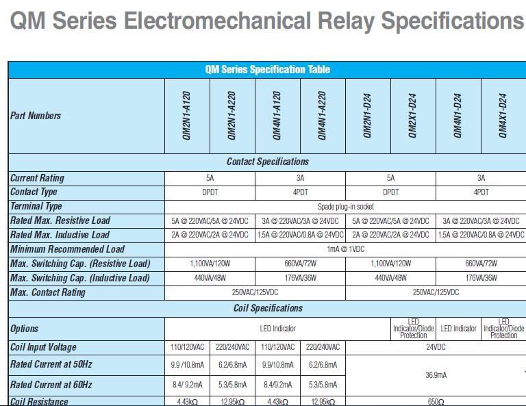
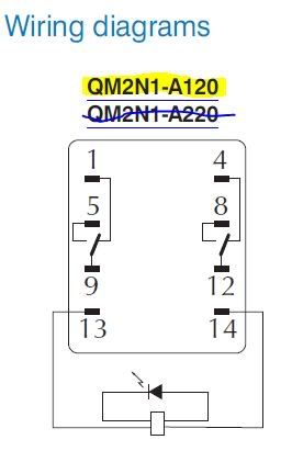
I am trying to understand the relay wiring diagram. Running 9.2mA of 120VAC across position 13 to 14 activates the coil that flips 12 & 9 (which is normally closed with 4, & 1 respectively) to be now closed with 5,&8 respectively.

Is this correct?

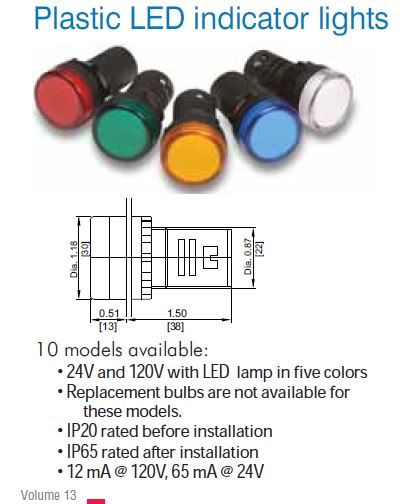
Now regarding the light which uses 12 mA at 120VAC, could it be in series with the 9.2mA Coil? Is that a no-no?
 
terminals 13&14 are only for powering the indicator lamp.

1,5&9 and 4,8&12 are the two switching poles.
a conection between 1&9 will normally be closed (untill the switch is pushed), 5&9 will normally be open (untill the switch is pushed).

a conection between 4&12 will normally be closed (untill the switch is pushed), 8&12 will normally be open (untill the switch is pushed).
(both of these are independant, its like having two seperate switches controlled by only one lever/button)

there are no trigger coils in these, they are switches not relays. even if there were, i would not put the indicator light in series with a trigger coil. do it in parallel.
 
I'm pretty sure they are relays. Just can't seem to get a full grasp on my wiring diagram, and why I keep putting indicator lights in series with the coil on these relays. I need to wrap my head around this a bit more perhaps...
relay1.jpg


So what happens if you put a 12 mA indicator light in series with that activating coil? Does the coil blow? Does it drastically shorten the life of the relay?
 
terminals 13&14 are only for powering the indicator lamp.

1,5&9 and 4,8&12 are the two switching poles.
a conection between 1&9 will normally be closed (untill the switch is pushed), 5&9 will normally be open (untill the switch is pushed).

a conection between 4&12 will normally be closed (untill the switch is pushed), 8&12 will normally be open (untill the switch is pushed).
(both of these are independant, its like having two seperate switches controlled by only one lever/button)

there are no trigger coils in these, they are switches not relays. even if there were, i would not put the indicator light in series with a trigger coil. do it in parallel.

There are coils, the QM2N1-A120's are definitely relays, see here:
http://www.automationdirect.com/static/specs/qmrelays.pdf

Terazza - not sure why you have pictures of LED lights there...the LED indicator in the relay is already enclosed in the relay. That's the little triangle thing in the diagram. It's wired in parallel with the coil, not series. If you wanted to add an external LED light, like you have shown, I'd add it in parallel with the coil as well, so as to not screw up the current flow through the coil...

Wait, I get what you're asking. No, don't wire it in series. Loads add in series, (resistances add in series), so your coil wouldn't get enough juice. Wire it in parallel.

(Edit, we posted at the same time, so to answer your "what happens if it's in series"....if it's in series, then the resistance of that loop of the circuit will be much higher. The coil won't get it's 9.2 mA of current...it'll probably get closer to 5 mA, (seeing as the light pulls 12 mA by itself, and doing some back of the envelope guestimation). This won't "blow the coil", but it could be below the amount of juice the coil needs to fully engage the relay, and cause the relay to just plain not work)
 
Thanks for the clarification, I think I understand things better now... I have another question about a electrical contactor, but need to look up some info on it before I raise my question. Again, thanks.
 

Latest posts

Back
Top