Need help wiring 3 Position selector switch for Brewtroller

Homebrew Talk - Beer, Wine, Mead, & Cider Brewing Discussion Forum

Help Support Homebrew Talk - Beer, Wine, Mead, & Cider Brewing Discussion Forum:

This site may earn a commission from merchant affiliate links, including eBay, Amazon, and others.

EuBrew

Well-Known Member
Joined
Apr 22, 2009
Messages
607
Reaction score
33
Location
Columbus, OH
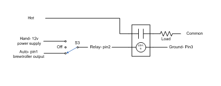
I think I've finally figured out the wiring for this but can someone please verify my drawing below?

Brewtroller has a 3 pin header designed to wire to a SPDT switch.

The three pins are
1 brewtroller (auto control)
2 Relay (activates relay for device)
3 is ground.

The BrewTroller brings all of it's output to ground when they are "ON", so do I have this figured out finally???
3Position%20Switch%20wiring1.jpg
 
Ahhhh... I get it. Your diagram is the backside view of two contact blocks...

Schematics are way easier for me. I have a hard time with you crazy kids and your visual representations... :D

So pin2 is on the BT, but is used to directly activate a relay (SSR). So pin2 is basically a digital input? Is that right?

If that is correct, then wouldn't the output from the auto side also tie into the relay pin 2. The ground, would be the return route???

Without really knowing what the pins are and how BT works, this is what I think is right...

BT_threeway.bmp
 
OK so following the logic about what each pin is from jcdillin at brewtroller and the info from the board pinout in the installation manual I get this.

From pinout on installation manual
HLT - MLT - KET Switch Headers (JP1,2,3)
I assume this is the same for JP1-JP16 on the relay board

1-2 = Auto
2-3 = Manual(ON)
0-0 = Off

From jcdillin
Pin 1 = BrewTroller
Pin 2 = Relay
Pin 3 = Ground

On a switch when pin 1 and 2 are closed BrewTroller is in control (auto)
when pin 2 and 3 are closed you have manual control (on).

Then my drawing should look like this, the left side represents 2 NO contacts on the back of a 3 position selector switch, the right is the schematic from a 3 pin header
3Position%20Switch%20wiring1.jpg
 

Latest posts

Back
Top