Home made peristaltic pumps

Homebrew Talk - Beer, Wine, Mead, & Cider Brewing Discussion Forum

Help Support Homebrew Talk - Beer, Wine, Mead, & Cider Brewing Discussion Forum:

This site may earn a commission from merchant affiliate links, including eBay, Amazon, and others.

silverbrewer

Well-Known Member
Joined
Apr 19, 2009
Messages
167
Reaction score
1
Location
Birmingham UK
I have just tested this pump, and at 120 RPM got a flow rate of 4 USGPM or 15 litres!
Pic080.jpg

I hope no one minds me re-posting this here as I put it in the wrong place initially ("peristaltic pumps" in the equipment section.) And I do not know how to rename the title or move it, so perhaps a moderator could do that for me and put the previous posts here instead.

I will follow this up with more details if there is interest in others constructing these pumps, but for now it is looking very promising, and cheap.
 
What is the ID and length of the tubing you are using? The 4 GPM is a very impressive flow rate for a peristaltic pump and motor of this size.
 
Hmm...

Looks like I have yet another distraction from studying for finals. I've actually thought about making a p-pump but didn't think I'd be able to pull decent flows.

I guess I'll have to talk to my buddy that works at a skateboard shop - see if I can get some free wheels. Reminds me, I need to toss him a homebrew.
 
Thanks for all the positive comments, and please check out the posts on this subject that I put in the "equipment and sanitation" section by mistake. There are details there of a pump made by Jonathon in Australia, but he did his on a computer and an automated mill, because he is clever, and a lucky son of a .......

I will see how high it pumps in a few days when I have done a proper job of the drive system. (I want to pin the spider to the shaft with a removable pin)

The tube internal diameter is 1/2" and it is getting squeezed against a wall that has a 6 5/8" radius (160 mm) Slower tests got a minimum reliable flow of 0.39 USGPM (1.5 litres per min). The 120 rpm test that got the 4.0 USGPM flow rate and also the slow test, were run with the pump sucking the water out of a container that had a water level that was 17" below the table.

OK, the point is taken that the pump is a bit big, but there are so many options open as you decide how big to make it.

Smaller tube, multiple tubes (either doing separate pumping tasks or pumping in unison) and varying rpm (probably with an upper limit of 150 rpm at a guess) give a multitude of choices.

The important things are that the rotating spider with the wheels must be exactly in the centre of the wall, there must be at least two wheels squeezing the pipe at any time, and the wheels must squeeze the pipe so it is completely shut when it is pinched. The wall does not have to be a complete circle, in fact, if you put wheels on a Caterpillar style track instead of a rotating set of arms, the pipe could be straight!! but I will leave it to someone else to engineer that version...

The flow is determined by how big the pipe is and the surface speed of the wheels.

I will post more pictures as the construction should be obvious once you have seen an exploded view of the thing, and as details are going to vary depending on how wide your wheels are, what pipe you use, and what materials you have. This can all be done by hand with a decent pillar drill, and some carefull sanding, like mine, but if you can use a three axis automated mill, things will be a cinch.

All my "plates" are held together by 4 steel pins, or dowels at the moment, and I will drill and tap the ends of these so they act as a dowel to locate things and also clamp the thing together! At the moment it is held together by luck, and the odd clamp.

My gut feeling is that I am going to make two pumps a bit smaller than this one, using 1/2" tube as my main pump (and it's backup) and a pair of much smaller ones, each with twin tubes to perform the sparge pumping, (plus backup) These will all sit on the same shaft and I will engage a pin into whichever pump or pumps that I wish to use.

Pictures to follow in a few days.
 
This is a great project, keep us posted as the generally used pump is the March pump that i'm not impressed with. With all the lost prime problems members have and the amount money they are asking for them and needing two I have never purchased a March over the years just borrowed. The results alone had made up my mind years ago and saved my money instead.
hey keep posting your progress, i'll check your other postings in the other section of the forum, thanks.
Carl.
 
I love it, I don't care if it's the size of 4 march pumps. After banging my head against the wall with priming issues I would love to have a pump that just works. This is for sure a step in the right direction.
 
Just adding up the price of two March pumps plus the priming problems i'm glad to read about them over the past year as I have not made the step yet to buy another pump as I have a old shaft drive stainless steel pump with a packing gland still in use. It has a drop every 4-5 minutes, enough to lube the square rope graphite seal material. Just turn the packing flange ring a bit tighter when required. This a borrowed pump off a lab friend that I can not get ownership of but keep trying.

I picked up a curbside tennis ball pitcher a trash item, in it was a Von Weise Gear Comany motor. It's complete with the 1/30 hp 90 VDC with the speed control, takes 120 VAC to run it. The motor draws .48 amp, 18 to 114 RPM's output. A free item just need to build a pump. If too weak the Von Weise company must have larger more powerful motors with speed controls if needed on the net. Just and idea for a 90 volt DC motor with a speed control. It may also end up just as the HLT stir motor turning a 9" bronze racing prop at a low speed as the pitch is 10 1/2", cupped and mean looking from the 50's outboard racing era.
I was thinking about the spare parallel gearmotor 120 VAC with 60 RPM's fixed speed motor that draws 1.48 amps with a 1/2" output shaft if it could be used as a pump drive but then I must have a bypass valve to control the fluid flow or a voltage control on the motor like a light dimmer as it might cause overheating problems doing this? I'm just working with what is in storage pile of the pack rat in me.

With aluminum stock, time on the lathe a twin pump with flanged ball bearings, spacers machined a single motor drive twin pump could be born. Use steel alignment pins then bore both tubing channels together. Assemble with Dutz fasteners for quick servicing or tube changing if needed.
For over a $300 investment for two March pumps this also has me thinking for over a year hence why I haven't become another victim of more problems on brew day fighting the March pumps. My friend has and now has it mounted on a camera ball that locks in any position. What a PITA I don't need for my $300 plus spent dollars.

As silverbrewer stated, the concentric item is an issue that must be correct with these pumps and if it were my pumps a couple spare tubings would be all that's needed should a tubing failure happen on brew day. A quick fix with it and more on.
I vote this thread as a sticky. With the vast spread of background of brewers there should be more replies on this topic. I'm flat on my back or house limited at the most so standing at the lathe and Bridgeport is out of the question for me. Come on others and chime in on this one.
 
Agreed it should be sticky and it also should be combined with the other thread.

I think we should try to get a set of cad files together so anyone can build their own.

As soon as I can get something drawn up in cad I will be cutting mine out on the cnc, I am going to be redoing my stand and kicking the march pump to the curb if I can get one of these pumps working good.
 
Subscribed! Wish we could find already built items to combine for completion. Simple CAD drawing would be a great help though for from scratch construction. I will be watching this thread!
 
We also need to get a good idea of the maximum flow rate we require and also the flow rates required for each process. I am only just starting to build my new brewery, so cannot comment. USGPM seems way too much to me.

If doing RIMS as per the "Brew Magic" video, what flow rate is employed there? It is very small, and might require a smaller pump, as will sparging. Could someone post flow rates for these processes and any others so I can start on pump size decisions. Remembering that two pumps (read two tubes in a single pump housing) will be needed for sparging and that they can be run in unison to get double the flow rate for other processes.

We must also be cautious as we have no idea how long the tube will hold out and how soft it gets when hot, so don't chuck out the March pumps quite yet.....

I'm going to be busy with chores for a week or two, but my next phases of this project will be to sort out more pics so you all have a clear idea of what I did, then get the drive coupling better engineered, which I have virtually done now anyway. Then with that sorted, I will see how high it will pump (several feet is my guess) I will then rig it up and do some 24/7 testing to see how the tube holds out.

Bear in mind that this is only a quick wooden mock up, and that this thing is best made with really good bearings, nice hard smooth wheels and perfectly concentric parts, so it will be best done on cad driven machines, in nylon with ball race bearings......but at this experimental stage we can ease up a bit on all that per-nicety stuff.

Give me suitable flow rates guys.....

The current project getting done at work is a home made "Blichman" false bottom.....punched out my first practice hole today!
 
Another successfully test.....

At 105 RPM and using the centre of the pump as a datum, it sucked the water up out of a bucket 4 foot below itself and then pumped it another 10 foot straight up a bit of 1/2" stainless pipe..............so that's "beerthirsty's question answered ....14 ft .......

I did not even try to measure the flow as it is near dark now, but off the top of my head I would say it was hardly any slower than before...this baby really works...

The limits are going to be how powerful the motor is and at what pressure the silicone tube explodes..
 
2GPM would be fine for how I use a pump. I don't have any of the equipment to make this with CAD drawings etc. If i built one it would probably look similar to your prototype but maybe smaller and using a windshield washer motor.
 
Your specs are indeed impressive. I built one a couple years a go, but had problems with tubing creep, so discarded it. I would run the motor slower simply due to the fact that the only two real factors for the tubing life is the number of compressions and the heat cycle you get with each compression. Due to these concerns I found this single lobe pump(way overpriced) which would give about three time the life of a three lobe pump. Eccentric Pumps, LLC
If any of you CAD geniuses could do something like this we would all be in heaven. It seems like it would be easier since we a talking a complete circle instead of a partial one, but what do I know, I'm not a CAD genius.
Also agree with conpewter 2 gpm would be just about perfect.

Very nice Eccentric Pumps, thanks for posting beerthirty.
Their 2.5 GPM pump looks like they use a sprial for the 360 degree roller contact. They keep mentioning friction of a shoe or slider vs a roller generating heat to the tubing. The original thread starter has rollers hence no added friction or heat buildup.
The smallest unit at 125 to 150 PSI wow, plus the 65 pounds weight, i'm afraid to ask what two of them would cost. I bet more than my last couple home made brewing systems in total costs. Would be nice especially as a double pump single unit design.
With in and out fittings for their hose connection this would eliminate the tubing from creeping around in the roller direction, just an opinion here.
 
The 5 gpm eccentric pump requires 750 in lbs @ 150rpm (~1.8HP ). This may not be all that cheap after all. That said, I am pretty sure I don't achieve the 7 gpm that my march pump is speced at so 5 gpm may be overkill.
 
It looks like "tecnic" made his wall by hand, proving cad is not the be all and end all! The single roller idea is very good and does everything it says on the tin! It works fine as long as the setup has sound bearings and is well engineered, as the forces of squeezing the tube are not counteracted by other rollers, so a continual sideways strain is created that will be no problem as long as the bearings are nice and massive. Also the tube MUST overlap so the single roller always completely squeezes the tube at some point or the pumping pressure is lost. (unless a non return valve is introduced into the system, this is what I did on my mates farm pump that was a single roller affair using an old compressor crank and crankcase, and we could not overlap the tube. we can't use non return valves though, so don't even think about it.) A good starting point for anyone thinking to use the single roller approach would be to use the crankshaft and crankcases of a small motorcycle engine, (say Honda cub 90 or 125 cc single) and put the tube around the inside of the crankcase where the generator flywheel used to live. This gives an easy way of getting nice big bearings and a concentric wall to run the tube on, with a potential for about 2 usgpm or thereabouts.

On my wooden Mk1 effort, before the rollers get to see the water and are struggling to pump just the air, there is a very slight "cock up" somewhere that allows a tiny amount of air to pass the rollers. I think it happens as two of of the rollers pass the tube entry points nearly at the same time, and have to rely on only the single roller and the quality of the bearings to keep the tube squeezed. This means that to get the priming ability with only air in the system I need a good amount of revolutions to counteract the slight leak...once water gets into the tube, all is well. This proves that quality construction is paramount! With no air leak, this type of pump should suck air with no problem and self prime to several feet or more, so back to the drawing board. My skateboard wheels need to be about 1/16" wider to ensure a complete squeeze, so my slight air priming problem is sorted.
 
Heat buildup will occur even with rollers due to compression and expansion. Take a balloon and stretch and release it several times in rapid succession then feel the temp of the balloon. It is much warmer. Although each stretch cools it, the release heats it back up. Unfortunately it is easier to heat than to cool, so it gets a little warmer with each cycle. As it gets warmer the rate of deterioration increases, therefore the cooler it can run the longer it will last. With fewer rollers you reduce the heat cycle.
The pumps in the link are indeed expensive. I priced one out at $1800. Way out of my price range. But I did like the design and it seems like it would be just as easy to build as any other style of peristaltic as long as the housing can be centered.
 
Your specs are indeed impressive. I built one a couple years a go, but had problems with tubing creep, so discarded it. I would run the motor slower simply due to the fact that the only two real factors for the tubing life is the number of compressions and the heat cycle you get with each compression. Due to these concerns I found this single lobe pump(way overpriced) which would give about three time the life of a three lobe pump. Eccentric Pumps, LLC
If any of you CAD geniuses could do something like this we would all be in heaven. It seems like it would be easier since we a talking a complete circle instead of a partial one, but what do I know, I'm not a CAD genius.
Also agree with conpewter 2 gpm would be just about perfect.

Look at the replacement tubing they are asking for the Eccentric Pumps company. The price of one tube is way more than one March pump, damn what a deal killer of a pump purchase besides replacement tubes by them.
Maybe ok from a manufacturing company that has deeper pockets than you and I as only home brewers.
 
One of the limiting factors in getting a HERMS system to ramp quickly is the rate of flow.
Assuming grain bed compaction doesn't replace the flow rate as the limiter, this peristaltic pump could be a great solution to quick ramps using HERMS and RIMS.
In my system, my March manages about 8 litres / 2 US Gall per minute.
I would like 3-4 gpm. from a peristaltic pump to make it a significant change from the March for the above purpose.
The priming advantages aside of course.
So Silverbrewer have you arrived at any design specs we can pass to the CAD guys?
Don't mean to rush you....

Cheers.
 
Yorg....the mk1 has 1/2" pipe on a wall that is 160 mm radius. The construction leaves a bit to be desired, but once primed it will run between 0.55 litres pm (0.5 us pint) at 8 rpm to the max I have run it at so far that was of the order of 120 rpm and 4 usgpm. I have just had it pump vertically up a 15 ft length of 1/2" stainless tube with no problems at 105 rpm, so that is quite a big flow range.

My main concerns at the moment are how it will perform when asked to pump hot liquids, (as that is what it is going to be dealing with, even though it can be placed after the cooler during boiler to fermenter operations, it will still see mash temps in my rims) and how the tube will stand up to the rollers giving it a constant hammering....

I cannot really test the tube longevity in the mk1 setup, as the MDF crap it is made from gives off a lot of wood and glue dust that settles on the outside of the pipe, so it would not be a fair test until it is made from something nicer like nylon and is constructed in such a way as the tube and walls etc are sealed from outside contaminants.

That said, I have it set up to run at a constant 46 rpm, (that will give 4.6 litres per min.) and over the next week I will be running it all the time I am at home, to give it the nearest I can to a continuous test. So far it has run for a couple of hours at that speed setting.

When I get a free weekend, I will set up a similar test, but at high temperatures.

The Mk 2 is taking shape, and might be a single wheel, running in a 3" length of 1/4" wall thickness alloy tube of about half the size of the Mk 1. I saw a whole bunch of alloy tube remnants when I went and bought a length of stainless 1/2" tube last Friday, so I will be buying a bit of something suitable as soon as I can. I have bought three conveyor wheels from RS, item no 2352224 ...... that has good solid ball races and is 2" wide, 1 7/8" dia and runs on a 15 mm shaft. http://uk.rs-online.com/web/search/...od=searchProducts&searchTerm=2352224&x=15&y=8

Having my lathe run the pump is a brilliant idea.....I have fitted a potentiometer into the lathes existing drive electronics that gives zero to max revs in whatever gear setting I put the lathe in. From outside the shed, on a brewing day, the potentiometer is a pump control knob, and from inside it gives the lathe infinite speed control when used as a boring old lathe (Pun intended)

I have taken pictures and a video, and will post them when I get a bit of time and also work out how it is done!!
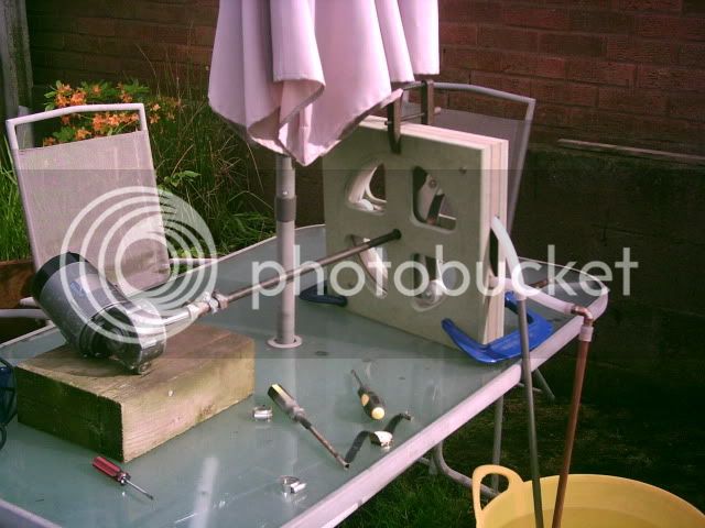
 
I get the impression that running mk1 at something like 100rpm wasn't giving you the impression that this would be a normal running speed. Would that be because of the MDF construction, or inherent in the design?.
Is mk2 an improvement for same purpose as mk1 or is this version for something else altogether - I think you had mentioned something about a spererate pump for sparging?

Since I don't, and i suspect most others don't have a lathe hanging about, what power/torque specification would a motor have to be? I thinnk you mentioned something about a wiper motor - are you thinking it would do the job.
Would a wiper motor be speed controllable via pulse width modulation do you think?
Cheers.
 
How about picking taking a piece of 6" schedule 80 pvc pipe and cutting off a 1" slice of it. then you could sandwich that between two pieces of mdf, steel, etc. I can't figure out how to make the roller assembly without access to a machine shop.
 
These pumps may well work fine at 100 RPM, or even faster? Now that I have shown that they may have the capability, it needs someone to make a proper one, then use it for a year or so before we can be absolutely sure. (I am going as fast as I can) The same goes for the sizes of motor required. Using wiper motors would enable everyone to have a cheap power source, but that may be wishful thinking. Reducing the speed of an electric motor electrically reduces it's torque proportionally (I think) so it is much better to get the speed down to whatever you need using reduction gearing of some sort, be it chains, belts or gears. The good news is that if you reduce the speed of a motor mechanically you INCREASE the torque proportionately! If the dérailleur gear sets from push bikes can be made to work back wards, that would do it and give you a selection of gears to choose from! Some sort of simple chain tensioner should keep the chain from falling off.....Pulse width modulation would do it as well (but with the reduced torque problem), so get a sizable scrap motor from somewhere and then gear it down, then speed control it for fine adjustment. It most likely won't be pretty, but pretty costs $1800! so settle for ugly.

As soon as I get my 15 mm drive shaft coupling from RS I will connect my Mk1 pump to my large motor rather than my lathe. (this motor is in the pics and is about 4 times bigger than a wiper motor, it is geared down to 120 rpm mechanically and also has electronic speed control on the 240 volts) If this works, I will then try it on a 12 volt wiper motor and see how that manages. My guess is it will get very hot, but who knows. In the meantime, I am endurance testing the MK1 at 40 rpm on the lathe. It has done 8 hours so far. (2X4hrs)

The Mk 2 is being made mostly because of the crap MDF construction of the Mk1 and the fact that the skateboard wheels I used need to be a tad wider to fully squeeze the tube completely, this lack of squeeze at the very edges is causing air to pass the rollers slightly and so it needs a few revs before it primes. Fully squeezed, it will prime at any speed.
Sjlammer...please note that the 1/2" tube needs rollers of at least 27 mm wide, so a bit over 1"

I don't see the need for such a high flow rate as 4 USG PM, but feel free to enlighten me if I am wrong...I was going to make two pumps using 1/2" silicone tube and a bit smaller wall radius, say 100 mm, using 1/4" thick walled aluminum tube, or some of the large plastic tubes used for water mains under the street! Each pump will be made wide enough to let the 1/2" tube overlap, so it then only needs a single wheel, but that wheel needs to be at least 60 mm wide. So that will probably be two bits of pipe about 6" long. Each bit of pipe will have to have an arm to hold the wheel and two solid end plates to hold the bearings and seal out any dirt, unlike my Mk1

The plan would then be to use one pump to put hot liquor into the mash tun, say 60 rpm to get about 6 litres per min) one pump to circulate the mash liquor during RIMS, say 20 rpm to get about 2 litres per min, both pumps to sparge, at say 5 rpm to get 0.5 litres per min. Then either one or both pumps to circulate the boiled wort through the plate cooler and then back to the boiler to swirl the cold break at 60 rpm and 6 or 12 litres per min, and then the same to transfer the cold wort to the fermenter.

My biggest fear is that the pumps have the ability to suck at a stuck mash until it solidifies into concrete, so hopefully the rims process will settle the mash out to a nice filter! March pumps will just sit there waiting for liquid in the same situation....anyone wish to comment?

Do the flow rates above make sense? If you want higher flows to get HERMS fired up fast then just use two or three pumps on the same shaft, or two or three tubes in the same pump...just make everything wider and use a strong motor!
 
Fantastic news guys....The Mk 1 pump turns just fine with a windshield wiper motor.

The thing is out of a Range Rover Discovery, and has two speed settings which under no load give 60 and 40 RPM. driving the pump on the faster setting the pump slows down to 37 RPM and pumps 3.55 litres per min, which is 0.937 US Gallons.

The motor is going to get mighty hot, but hey, you've just got to make a small water jacket for the motor case and either cool it with tap water or knock up another tiny peristaltic pump to flow some water through it !!!! I will run it until my leisure battery gets low, or the motor melts, whichever happens first.

Houston, we have cheap pumps......
 
I'm currently working on drawing up a model in solidworks, after it's done I can export it to other formats for whatever cad software people may have.

Soon as I have it finished and find some material I am going to cut one out on the cnc and see how it works.
 
Yea I'm dead chuffed with it! I have had the wiper motor running for a hour and it does indeed get hot! Smokin would be a better term to use, so anyone going down this route had better (read must) source a wiper motor with a steel motor body rather than an aluminum one so a copper water jacket can easily be soft soldered on, and set to work.

To connect it to my 15 mm dia pump drive shaft, I made up a 2" length of 15 mm dia steel and drilled and tapped a thread concentrically in one end. This just screwed onto the motors output shaft until it hit the start of the splined cone that seems to be universal on these things. I then clamped the two 15 mm shafts together using a proper shaft coupling with decent clamping screws. Jubilee clips and a bit of old hose pipe will not stand the torque!

An hour long test at that temperature means that the motor is basically up to the job and we just need to stop them dying by getting the temperature down to reasonable levels. From previous work, water cooling the motor bodies of electric motors "in distress" I can say that water cooling is mighty effective and would expect the motor to not get past luke warm if a water supply is rigged up.

Yeaaaaaaaaaaaa!
 
So are some photos of my pump design. Now these are based on Jonathans pump design in the other thread. I really liked the look of the pump and how compact it was.

This is designed for 1/2" tubing.

Here you can see the main case, you would just cut two of these out and then sandwich them together.

maincase.jpg


These are the covers, again you would cut out two of them. I'm planning on cutting them out of 1/4" acrylic

cover.jpg


And here is the beginning of the assembly, I still need to design the rotor and figure out how to mount bearings.

pump.jpg


If anyone wants a copy of the drawings please let me know, or I will be posting a download link once I have the rotor finished.
 
Back
Top