Being inspired by so many great-looking projects on this forum, I decided to build myself a keezer. I actually still haven't finished my electric brewery so some might say this is a bit premature, but when you're waiting on a crucial part and you run into an open box GE 7.0cf chest freezer on sale for $150 at Home Depot, a more religious man might take that as a sign.
The first thing that bothered me about this device was that this was in the description
That might sound mundane enough but what it really means is that it has a light on it that tells you it is plugged in and the thermostat is set to anything but "Off". "C'mon guys," I complained to my buddy who had come over to share a glass of a new scotch he had found, "you can't make the light only come on when it is on?". "If you're so smart, make your own thermostat," my friend replied. That's not something you say to an engineer. We beleive that if it ain't broke, it doesn't have enough features yet. So let's make a thermostat!
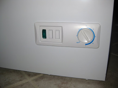
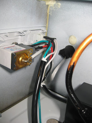
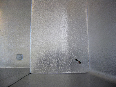
So here we have the original, boring GE thermostat with its condescending green power light and vague temperature knob. I don't know what units this thing is in, but where I come from we have more temperature values than 1 to 9.
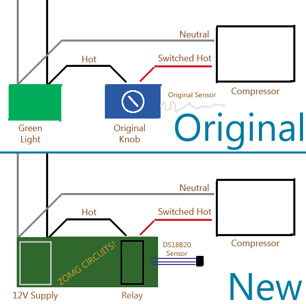
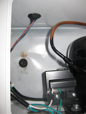
And from the inside you see it is just a relay on the hot line of the compressor. I laid down to look inside the compressor compartment and almost fell asleep it was so basic. But look at that! There's a thermowell hole going into the freezer which would sure make a convenient place to put my temperature probe.
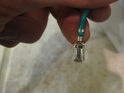
For those who don't know, to remove the connectors from the existing thermostat, there's a little tab in the center of each connector you have to push down to disengage the locking mechanism and they pull right off. If they don't come off easily, the mechanism isn't disengaged
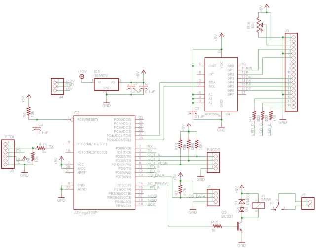
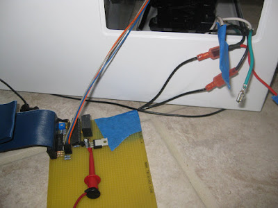
I pulled their gas tube out and eyeballed it against a DS18B20 one-wire temperature sensor. They looked to be about the same size, and the transistor easily slipped into the thermowell. I set to work and gathered up components. Parts ran under $15 plus $15 more for the LCD. Basically it is an ATmega328P microcontroller talking to the LCD via an I2C port expander (MCP23008), PWM lines controlling the RGB backlight color, a connector for a rotary encoder to set parameters, and a $2 5V A/C relay. I added some connectors and slipped myself into the hot line of the compressor. I've also got a 12V power supply for the thing which will be wired in to the existing wiring as well once I get that far.
This is where I hit my first snag. While the DS18B20 fit into the existing thermowell, about two or three inches into it, there was a point where the tube narrows that the probe won't fit through. The DS is about 4.5mm wide and the existing gas tube was about 3.2mm wide. Poking around in the hole, it felt like the narrowing was only in the bulkhead going into the freezer, and then widened back out on the other side. I have a tool for making narrow holes go away: a drill. Inserting the drill at a bit of a wonky angle I fired it up and I could feel the bit cutting my way to freedom with tragedy stuck. The cheap bit bound up and snapped off in the hole. My suspicions were correct though. The piece of the drill bit that was on the other side of the hole was in a larger tube than the narrow bit and, welp, wasn't coming back out from this side.
"How can I make this situation worse than it currently is?" I pondered overnight. There's no going back. The drill bit chunk in the hole meant the old thermostat won't go in all the way any more, so I was dubious if it would function properly. If you're going to break something, break it good. I wanted to get my temperature probe inside the chest without running any wires on the outside so I considered cutting into the hump. Are there any coolant lines in there though?
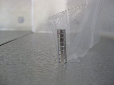
The answer was just a magnet away. Magnets. How do they work? Well the inside of the chest freezer is lined with non-ferrous metal, which means the magnet won't stick to it. The coolant lines are made from ferrous metal, which means you can feel the lines by waving a magnet around along the walls.
From what I could feel the top of the hump doesn't seem to have any lines running through it. However, the insulation here is about 4" thick so they could be buried in there. The side of the hump is loaded with coils. I busted out the hole-maker and made a hole down into the compressor compartment. I'll clean this up a bit with a nice rubber grommet at some point, but I'm also going to run wires for a DC air circulating fan through this hole so I'll do that first. From the top:
And inside the compressor compartment. I reused the black gunk that was holding the original wires in place. The red splotches on the pristine white metal may or may not be human blood extracted through endless toil.
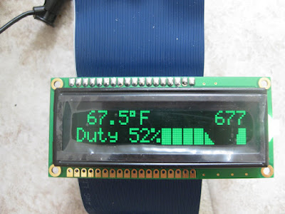
Here's what the LCD looks like currently. It has the current temperature, run time, duty cycle, and a bar graph of the temperature. The color of the text changes depending on what the controller is doing. The RGB LED is fully PWMed so I can mix it to get any colors I want. Once I finalize all this I'll mount it in the space occupied by the original thermostat.
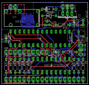
I'll keep updating this thread if there's interest with some less ghetto-looking results. I didn't want to etch a PCB if this wasn't going to work, which it almost didn't. Up next is that, wiring up the knob to control the temperature, getting it into a small radio shack enclosure, and mounting the LCD to the fridge.
Why didn't I just buy a single stage temperature controller? Well, if I did that there'd be a lot lower change of me ruining something, so where's the fun in that? Plus this is pretty small (the circuit board is 2"x2"), connects into the existing wires (no Lowe's run to buy an outlet or power cord to cut up), I can customize it how I want, and most importantly it has a freakin' graph!
The first thing that bothered me about this device was that this was in the description
Exterior power-on light shows you at a glance that the freezer is turned on
That might sound mundane enough but what it really means is that it has a light on it that tells you it is plugged in and the thermostat is set to anything but "Off". "C'mon guys," I complained to my buddy who had come over to share a glass of a new scotch he had found, "you can't make the light only come on when it is on?". "If you're so smart, make your own thermostat," my friend replied. That's not something you say to an engineer. We beleive that if it ain't broke, it doesn't have enough features yet. So let's make a thermostat!
So here we have the original, boring GE thermostat with its condescending green power light and vague temperature knob. I don't know what units this thing is in, but where I come from we have more temperature values than 1 to 9.
And from the inside you see it is just a relay on the hot line of the compressor. I laid down to look inside the compressor compartment and almost fell asleep it was so basic. But look at that! There's a thermowell hole going into the freezer which would sure make a convenient place to put my temperature probe.
For those who don't know, to remove the connectors from the existing thermostat, there's a little tab in the center of each connector you have to push down to disengage the locking mechanism and they pull right off. If they don't come off easily, the mechanism isn't disengaged
I pulled their gas tube out and eyeballed it against a DS18B20 one-wire temperature sensor. They looked to be about the same size, and the transistor easily slipped into the thermowell. I set to work and gathered up components. Parts ran under $15 plus $15 more for the LCD. Basically it is an ATmega328P microcontroller talking to the LCD via an I2C port expander (MCP23008), PWM lines controlling the RGB backlight color, a connector for a rotary encoder to set parameters, and a $2 5V A/C relay. I added some connectors and slipped myself into the hot line of the compressor. I've also got a 12V power supply for the thing which will be wired in to the existing wiring as well once I get that far.
This is where I hit my first snag. While the DS18B20 fit into the existing thermowell, about two or three inches into it, there was a point where the tube narrows that the probe won't fit through. The DS is about 4.5mm wide and the existing gas tube was about 3.2mm wide. Poking around in the hole, it felt like the narrowing was only in the bulkhead going into the freezer, and then widened back out on the other side. I have a tool for making narrow holes go away: a drill. Inserting the drill at a bit of a wonky angle I fired it up and I could feel the bit cutting my way to freedom with tragedy stuck. The cheap bit bound up and snapped off in the hole. My suspicions were correct though. The piece of the drill bit that was on the other side of the hole was in a larger tube than the narrow bit and, welp, wasn't coming back out from this side.
"How can I make this situation worse than it currently is?" I pondered overnight. There's no going back. The drill bit chunk in the hole meant the old thermostat won't go in all the way any more, so I was dubious if it would function properly. If you're going to break something, break it good. I wanted to get my temperature probe inside the chest without running any wires on the outside so I considered cutting into the hump. Are there any coolant lines in there though?
The answer was just a magnet away. Magnets. How do they work? Well the inside of the chest freezer is lined with non-ferrous metal, which means the magnet won't stick to it. The coolant lines are made from ferrous metal, which means you can feel the lines by waving a magnet around along the walls.
From what I could feel the top of the hump doesn't seem to have any lines running through it. However, the insulation here is about 4" thick so they could be buried in there. The side of the hump is loaded with coils. I busted out the hole-maker and made a hole down into the compressor compartment. I'll clean this up a bit with a nice rubber grommet at some point, but I'm also going to run wires for a DC air circulating fan through this hole so I'll do that first. From the top:
And inside the compressor compartment. I reused the black gunk that was holding the original wires in place. The red splotches on the pristine white metal may or may not be human blood extracted through endless toil.
Here's what the LCD looks like currently. It has the current temperature, run time, duty cycle, and a bar graph of the temperature. The color of the text changes depending on what the controller is doing. The RGB LED is fully PWMed so I can mix it to get any colors I want. Once I finalize all this I'll mount it in the space occupied by the original thermostat.
I'll keep updating this thread if there's interest with some less ghetto-looking results. I didn't want to etch a PCB if this wasn't going to work, which it almost didn't. Up next is that, wiring up the knob to control the temperature, getting it into a small radio shack enclosure, and mounting the LCD to the fridge.
Why didn't I just buy a single stage temperature controller? Well, if I did that there'd be a lot lower change of me ruining something, so where's the fun in that? Plus this is pretty small (the circuit board is 2"x2"), connects into the existing wires (no Lowe's run to buy an outlet or power cord to cut up), I can customize it how I want, and most importantly it has a freakin' graph!