How to build a control panel (part 1)

Homebrew Talk - Beer, Wine, Mead, & Cider Brewing Discussion Forum

Help Support Homebrew Talk - Beer, Wine, Mead, & Cider Brewing Discussion Forum:

This site may earn a commission from merchant affiliate links, including eBay, Amazon, and others.
Sorry Klaus, I just don't understand the concern. In fact, I think your idea's less safe the more I think about it. I do not recommend it.

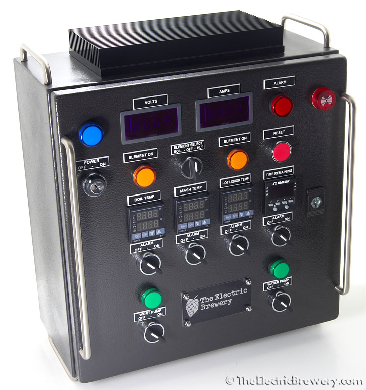
If you put in an extra SSR so that the red HOT to the element is off if the PID is not firing all you're doing you're adding a secondary OFF switch to the PID. But that's not a good idea. If someone wants to stick their hand in the kettle they should turn the ELEMENT SELECT switch OFF as that's a physical hard ON/OFF switch. The logic's simple: If I want to stick my hand in there I have to turn if off.

Now think of your way: Adding a second SSR for the red hot lines essentially adds a 'secondary' OFF switch to the PIDs. Someone may now think that they're ok to stick their hands in the kettle with the ELEMENT SELECT switch still in the ON position as long as the PID temp is set low enough such that it doesn't fire. That's not good. That's an inherently unsafe design as whether the element fires is controlled by temp/environment (if the air/water/wort temp in the kettle changes the element may fire). Adding a secondary conditional off is very dangerous as the person has to think about what they're doing. A control panel needs to have a simple OFF switch for cutting power, not something conditional or a second way. ON or OFF, nothing else. No conditions.

It's safer for the user to know that the only way to make the thing 100% safe to stick your hands in is if the ELEMENT SELECT is OFF. That cuts off both hot legs 100% *physically* from the element as per my design today.

Secondly, SSRs, when they fail, usually closed making this idea less safe too.

Thirdly, SSRs have leakage current. Even when off, some current gets through.

I really think the safest way to use the control panel is for the user to get it in their head that the ELEMENT SELECT switch has to be in the OFF position for power to be 100% cut to the element. That is exactly what happens with my design. I do not recommend you make the changes you suggest. It adds something which someone may think add some 'safety' which in fact it makes it more complex.

If something goes wrong with the grounding for whatever reason you could only get shocked when the element is actually firing instead of just selected to the on position.

ON/OFF controls need to be simple: If the ELEMENT SELECT switch is ON nobody should be unpluging stuff or touching elements. If the panel's on at all, you should not be unplugging/plugging stuff.

Kal
 
ON/OFF controls need to be simple: If the ELEMENT SELECT switch is ON nobody should be unpluging stuff or touching elements. If the panel's on at all, you should not be unplugging/plugging stuff.

Kal

Agreed, do not build a system that makes it safer (encourages) to play Russian Roulette with your PID. Think of the PID as a means of controlling temperature once the element is activated (and assume when "on" it is always active), not a means of cutting power to the element. That is not it's purpose. I have been following this thread and his website for some time and folks have made a lot of design alterations based on features, personal taste, etc., but I have yet to see anyone who made alterations to make it safer. I added an extra 15 amp fuse to protect my RIMS heating element circuit since the overall supply is protected by a 20 amp GFI, however, for HERMS this is unnecessary based on the relevant power usage of the elements and other electrical components and the guage of wire used, IOW, I made no improvements on his overall safety.
 
I have a question about my control panel in regardings to my PID and heating element.

My system is 120v with 1 heating element that is used in a RIMS tube. On my control panel, there is a PID and below it is a on/off switch and below that is a on/off switch for the alarm.

My question relates to how should I wire it so that the PID and element gets power.

There is also a master on/off switch that powers up everying, should that switch be wired in a way so that when i turn it on, it powers up my PID (and timer)? Or should it be wired in such a way that when i turn the switch on, the PID will not power until i turn the switch on that is below the PID? My concern is that if I do it this way, when i turn the PID on the element will fire. If i wire in a way that when I turn the master power on, the PID will light up and the switch below the PID will act as a element selector so the only way the element can fire is if this switch is turned to the on position. But then again, i thought the element won't fire because I have the PID and SSR?

Maybe I don't understand how the PID, SSR, and temp probe work? Since I am using it for a RIMS tube, the only time the element needs to fire is when I reach my target temp and then I turn off my burner, kick on the RIMS tube to hold that temp for a desired amount of time.

31811 005.jpg
 
I have a question about my control panel in regardings to my PID and heating element.

My system is 120v with 1 heating element that is used in a RIMS tube. On my control panel, there is a PID and below it is a on/off switch and below that is a on/off switch for the alarm.

My question relates to how should I wire it so that the PID and element gets power.
I would suggest wiring it up the same way I do my panel which I believe to be the safest way: PIDs and timer get power when the panel is turned on, but the panel will not turn on if the element switch is on (for safety reasons). This is called a safe start interlock. Just like your car: You can't start your car if it's in drive. It has to be park. Again, done for safety reasons.

See here: http://www.theelectricbrewery.com/control-panel-safe-start-interlock

Now your wiring and possibly parts are going to be different since you've done something completely different with RIMS and gas. I can't help you design your setup that as it would be hours of work to design draw out even after I figure out your design goals and budget. Sorry. I get asked every day "can you design a custom system for me" and I just don't have the time. Many have taken my design and modified it of course or simply taken ideas. I documented my build completely so that others could do as they please and get ideas from from it if they decide to not build a clone.

There is also a master on/off switch that powers up everying, should that switch be wired in a way so that when i turn it on, it powers up my PID (and timer)?
I would suggest it be done that way.

Or should it be wired in such a way that when i turn the switch on, the PID will not power until i turn the switch on that is below the PID?
That to me is overly confusing. I would wire it to work functionally in the exact same way I did mine.

My concern is that if I do it this way, when i turn the PID on the element will fire.
Not if you use a safe start interlock.

If i wire in a way that when I turn the master power on, the PID will light up and the switch below the PID will act as a element selector so the only way the element can fire is if this switch is turned to the on position. But then again, i thought the element won't fire because I have the PID and SSR?
The element *WILL* fire because you have a PID and SSR. The PID tells the SSR when to send current to the element based on how you, the brewer, have set the PID.

Kal
 
Thanks kal

i actually just went ahead and purchased the safe start interlock. Is that what these relays are meant for? When you buy it from oebay it says nothing about it.
 
I wasn't referring to any specific product. I was referring (among other things) to building a safe start interlock into the panel as a safe way to do things.

When I go here: http://www.theelectricbrewery.com/control-panel-safe-start-interlock
And click on the link for the relay it still works perfectly.

I list it as a "10A 8-pin 2-pole ice cube plug-in relay with 110-120VAC coil". Like all of my other items linked to on ebay it's important to check to make sure that you're actually getting what my search looks for. Ebay doesn't have 'products' so I can't link directly to items without them expiring after a week or two. So instead I use the search feature for ebay which is why you'll often get 10-100 items coming back. If I linked directly to products, every couple of weeks I'd have thousands of links to fix in my site as the auctions would expire. That would be a full time job. ;)

That said, the one you link to appears to be the one I used in my setup. Be aware that that doesn't mean that it'll work in your setup since your setup is completely different than mine. I have no idea how you will be wiring up everything or what other parts you'll be using.

This relay only supports 10 amp max too. In my setup it's used to switch a larger relay that supports the ~24 amps used by the control panel so that's not an issue. If you plan on putting your RIMS element and other things directly in series with this relay then it'll likely use more than 10A so this relay will not work for you. Whether a part is right for your setup depends entirely on how your entire setup is designed - you can't design it and buy one piece at a time. Design a working solution *THEN* buy what you need.

Kal
 
Kal,

When you have time, can you give me some overall dimensions of the safe start interlock relay? I looked at my control panel last night and I may not have enough room for this relay. My panel is 12x12x6. Being that it is so shallow, i already had to play around with it a lot to find room for my mechanical relays so the PID and Timer wouldn't hit them when i shut the door. If this relay is as tall as the other relays i doubt it will fit unless I can actually mount it to one of the sides instead of the back plate or door.
With socket, it's about 3" high, and the socket base is about 1.5" x 2".

Kal
 
Quick wire sizing question:

My control panel will be all 120v and I will have the following components in it:

The proper size lights and switches
Auber PID
Eagle Signal Timer (Identical to the Omega brand)
Relay for power in
Relay for element power (2000 watt element)
40amp ssr
hot and neutral buss
Safe start interlock

The control panel will be powering the heating element and (2) 1/25th horse power motors.

Can i get away with using 12 ga wire for EVERYTHING except the components that will use the 22 gauge telephone type wire.

I know that some of the components can use 14 but if I can get away with using one size, then why not?

Also, I will be installing a new outlet in the garage and putting it on it's own dedicated 20 amp circuit. Do you think 20 amps will be enough for what I listed? Or should I go 30? If I go 30 then i think my wire size may need to change again.
 
My control panel will be all 120v and I will have the following components in it:

Can i get away with using 12 ga wire for EVERYTHING except the components that will use the 22 gauge telephone type wire.
Voltage is not important. It's current. Current define wire size.

I know that some of the components can use 14 but if I can get away with using one size, then why not?
Because it's more expensive, harder to work with.

Also, I will be installing a new outlet in the garage and putting it on it's own dedicated 20 amp circuit. Do you think 20 amps will be enough for what I listed? Or should I go 30? If I go 30 then i think my wire size may need to change again.
You need to add up everything you're going to using in terms of power consumption, then take 80%.

Kal
 
Besides the heating element and pumps, how much would you say the panel is pulling in amps? Does the PID, Timer, ssr, and lights pull enough to even consider how many total amps you are using when you look at the big picture?
 
would tell you, but I shorted my amp meter :)

5500 Watt element ÷ 240 Volts = 22.91 Amps or 23 Amps
4500 Watt element ÷ 240 Volts = 18.75 Amps
3500 Watt element ÷ 240 Volts = 14.5 Amps
1500 Watt element ÷ 240 Volts = 6.25 Amps

each chugger pump is 1.4 Amp

so with two chuggers and the element should be around: 25.71

now if you are using a 4500 watt element: 21.45
 
Besides the heating element and pumps, how much would you say the panel is pulling in amps? Does the PID, Timer, ssr, and lights pull enough to even consider how many total amps you are using when you look at the big picture?

Less than 1 amp.
 
Besides the heating element and pumps, how much would you say the panel is pulling in amps? Does the PID, Timer, ssr, and lights pull enough to even consider how many total amps you are using when you look at the big picture?
About 0.1 amps (100 milliamps).

With everything running including one element and both pumps, the whole thing draws about 23 amps.

Kal
 
I get emailed almost every day "will you build me a control panel" so today I'm happy to announce that we're finally now doing exactly that!

Below are some final product pictures. I have to say I'm really impressed with the way they turned out. This is what happens when you get a professional to do the wiring and work for you. Makes me want to scrap mine! ;)

DSC_0025_panel.jpg


DSC_0028_panel.jpg


DSC_0029_panel.jpg


DSC_0032_panel.jpg


DSC_0041_panel.jpg


DSC_0051_panel.jpg


DSC_0055_panel.jpg


DSC_0046_panel.jpg


DSC_0048_panel.jpg


Kal
 
Those control panels do look very nice indeed. Looks like the location of the safe start interlock was changed and maybe a couple different types of components?
 
Those control panels do look very nice indeed. Looks like the location of the safe start interlock was changed and maybe a couple different types of components?
Correct! I added my safe start interlock a couple of years after I had built mine so an alternate location had to be found when I did it. When starting from scratch it made more sense to put it on the backplate. Same result however.

The power supplies are also slightly different and matched with the volt/amp meters. One of the benefits of being in control of the build from start to finish is that you can match up/pair items that work well together. In my DIY instructions I wanted to go as flexible as possible with parts so that whenever possible people won't be required to get *exactly* the same part as me. For example, in the DIY plans I spec variable power supplies which then allows the builder some flexibility as to which volt/amp meters they use as there are different manufacturers with meters that basically work the same way but tend to have different brightness levels. In the completely built version above the various combinations were tested until we found a good match.

The important thing is that no sacrifices in quality or components were made. A lot of work went into keeping the price reasonable without sacrificing the build quality at all.

Kal
 
Since you really how this down to a science now, if someone were to sit down and do nothing but build one of these how many hours of labor would be in it. Im on month 3. 1 thing at a time for me!
 
Since you really how this down to a science now, if someone were to sit down and do nothing but build one of these how many hours of labor would be in it. Im on month 3. 1 thing at a time for me!

That really depends on the person, their skill set, the tools they have at their disposal, and how meticulous they are. You could build this control panel pretty fast if you don't try and get things lined up 100% perfectly and cut corners. If you want it to look nice it'll take more time.

I'm completely guessing here but someone familiar with electrical stuff and with all the tools could probably build the control panel in a week or so of working evenings and the weekend. Maybe 30-40 hours?

It's really hard to say. It's also unlikely that all the parts will arrive at the same time so most people building it work on it as parts come in.

Kal
 
Since you really how this down to a science now, if someone were to sit down and do nothing but build one of these how many hours of labor would be in it. Im on month 3. 1 thing at a time for me!

It has taken me about 6 evenings and 4 weekend days to get to the point that I'm about to wire mine which I would say is 50-60% complete. Total I have spent about 45 hours on it but I am very very meticulous and have gone cautiously. Someone else might be able to do what I did in say 20-30 hours.
 
Hi art!

Yup! Very much so! (For those that don't know - Heathkit was a company that made hobbyist kits way back when that you'd assemble yourself).

We're just trying to figure out what kits to offer. Some ideas for control panel kits include:

(1) No pre-work done at all. You get all the parts but instead of having to source them everywhere and make sure you get the right parts, you get them in one spot.

(2) As above, but all enclosure holes professionally milled (cut).

(3) All enclosure holes professionally milled (cut), enclosure cable plate sealed/sanded.

(4) All enclosure holes professionally milled (cut), enclosure cable plate sealed/sanded, enclosure primed & painted charcoal grey.

(5) All enclosure holes professionally milled (cut), enclosure cable plate sealed/sanded, enclosure primed & painted charcoal grey, heat sink tapped/installed/sealed, wires soldered to XLR connectors, volt/amp meter cables ready to install (no splicing/soldering required), some screws cut shorter for handles and front plate logo. Customer only has to mount the parts, wire, and seal some of the components. Only tools needed are a screwdriver, wire cutter/stripper/crimper.

(6) And for sake of completeness: A completely built tested, and programmed control panel. (This is what was just announced)

We're still working out the details - suggestions welcome!

Kal
 
That really depends on the person, their skill set, the tools they have at their disposal, and how meticulous they are. You could build this control panel pretty fast if you don't try and get things lined up 100% perfectly and cut corners. If you want it to look nice it'll take more time.

I'm completely guessing here but someone familiar with electrical stuff and with all the tools could probably build the control panel in a week or so of working evenings and the weekend. Maybe 30-40 hours?

It's really hard to say. It's also unlikely that all the parts will arrive at the same time so most people building it work on it as parts come in.

Kal
The price for your US made control panel is cheap in my opinion.
In our area the minimum fabrication labor cost for an automotive control panel used to be between $55-$75/h.


Cheers,
ClaudiusB
 
kal said:
We're still working out the details - suggestions welcome!

Kal

I think the threshold should be up to and including the millwork. Get it to the point where ordinary household tools are all that's needed. I can cut a wire and wield a can of spray paint but I'd have to buy specialized tools to cut (nice) holes, safely.

A big question with a kit sale is how much post-sale tech support are you willing to offer? That might make the kit idea a bad idea for you. I'm happy with the community forum (i.e. no formal support) model but others might expect your personal cell number.
 
I'm glad to hear of The Brewing Network interview that is coming up this Sunday. Do you guys know anything about what you will discuss? I will be listening live.
 
I think the threshold should be up to and including the millwork. Get it to the point where ordinary household tools are all that's needed. I can cut a wire and wield a can of spray paint but I'd have to buy specialized tools to cut (nice) holes, safely.
Thanks for the feedback. One thing to keep in mind is that we may offer more than one level based on what people want or don't want to do themselves. Not everyone has the same skill set, even for things like painting with a can of spray paint.

A big question with a kit sale is how much post-sale tech support are you willing to offer? That might make the kit idea a bad idea for you. I'm happy with the community forum (i.e. no formal support) model but others might expect your personal cell number.
That is indeed something we are discussing. You can go to either extreme: Raise the price and offer 100% support and in some cases basically walk the person all the way through the build process, or lower the price and offer no support at all. It's a balancing act and is (again) something we're carefully weighing.

If you offer 100% support on everything based on what someone half around the world may do wrong (and ends up frying half the parts) you'll end up with cost that's above just building it ourselves using skilled staff in a controlled environment.

In the end (IMHO) the kit price has to obviously be lower than the assembled/tested panel price so support has to be in line with the price. I also feel that the kit price has to be lower than what someone will pay to go and buy the parts themselves. I feel my instructions are pretty clear and that most DIY'ers would rather save the $$. If not, the completely assembled/tested/programmed/with warranty panel is what I'd recommend. But that's just me! ;)

Kal
 
I'm glad to hear of The Brewing Network interview that is coming up this Sunday. Do you guys know anything about what you will discuss? I will be listening live.
Lots based on caller feedback/questions and just "Electric Brewing" in general. I think they also want to cover my brewing background just to set the stage.

Link to the show is here: http://thebrewingnetwork.com/shows/734

Kal
 
Just finished the wiring last night. Now only waiting for my fuses to come in from amazon and the new Life Insurance policy to kick in before firing it up. Actually, now that I think bout it, I guess I have to make all the probes, too. Looking forward to it!
 
Kshuler,

I sent you an e-mail about this before but didn't get a response. This is off topic but do you sell the hop stopper in your member photo? Or have plans for it. Thats really nice. Does it work well?
 
Wiring is done and I fired it up for a 1st test run. Truly Amazing, thanks Kal! Won't get a chance to brew on it for a few weeks, but I am definitely looking forward to it! Still need to tune the PIDs and the valve control system, but it runs great, both the kettle element and the RIMS tube. Your method of sealing things to the kettle is superb- completely leak free and it automatically grounds the kettle and RIMS tube at the same time.
 
Your method of sealing things to the kettle is superb- completely leak free and it automatically grounds the kettle and RIMS tube at the same time.

Agreed, my RIMS tube is leak free as well using Kal's washer/o-ring/electrical box sandwich. A lot of people on here have struggled with achieving that on that tube.

I still haven't made beer yet, but did make maple syrup this last weekend.
 
Hi guys,

For those of you that read Brew Your Own magazine, my home brew setup's been featured in the 'homebrew drool systems' section of the May-June 2011 edition. Just got mine in the mail today!

Weird seeing pictures of the setup in print instead of on a computer screen.

My "Electric 20-minute APA" recipe did not make it however. Unfortunate. It's the one that lots have said they really liked. It an all-late addition APA (dry hopped with Citra). For those that are curious:

The Electric 20-minute APA

Size: 6.0 gal (post boil)
Brewhouse efficiency: 95%
Attenuation: 82.0%

Original Gravity: 1.056
Terminal Gravity: 1.010
Color: 5.86 SRM
Alcohol: 6.0%
Bitterness: 37 IBU

Ingredients:
7.75 lb Standard North American 2-Row (78.5%)
1.75 lb Vienna Malt (17.7%)
0.375 lb Crystal Malt 40°L (3.8%)
0.5 oz Centennial (9.2%) - added during boil, boiled 20 min
0.5 oz Amarillo (8.2%) - added during boil, boiled 20 min
1/2 Whirlfloc Tablets (Irish moss) - added during boil, boiled 15 min
1 oz Centennial (9.2%) - added during boil, boiled 10 min
1 oz Amarillo (8.2%) - added during boil, boiled 10 min
1 oz Centennial (9.2%) - added during boil, boiled 0 min
1 oz Amarillo (8.2%) - added during boil, boiled 0 min
12 g Fermentis Safale US-05
0.5 oz Centennial (9.2%) - added dry to secondary fermenter
0.5 oz Citra (11.1%) - added dry to secondary fermenter

Notes:
Add 250mg potassium metabisulphite to 10 gallons water to remove chloramine.
Water treated with brewing salts to: Ca=110, Mg=18, Na=16, Cl=50, S04=275
1.25 qt/lb mash thickness. Single infusion mash at 152F. Sparge with ~6 pH water.
Boil for 60 minutes. Lid on at flameout with 0 minute hops.
Cool wort to 66F and aerate well. Ferment at 66-68F. Dry hop for ~10 days.

Kal
 
Back
Top