Ready or Not E-BIAB Here I Come....

Homebrew Talk - Beer, Wine, Mead, & Cider Brewing Discussion Forum

Help Support Homebrew Talk - Beer, Wine, Mead, & Cider Brewing Discussion Forum:

This site may earn a commission from merchant affiliate links, including eBay, Amazon, and others.

aubiecat

Well-Known Member
Joined
Dec 27, 2011
Messages
1,195
Reaction score
136
Location
Alexander City
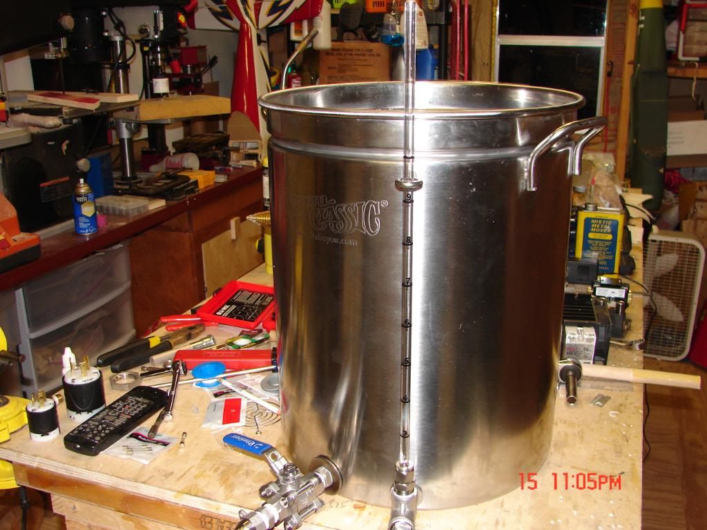
I have ordered all the gear to build an E-BIAB. To me, BIAB is best way to brew beer and nothing could be easier than an electric computer controlled BIAB. I have been inspired by the experienced members here who have posted proven methods of fabricating and using electric brew equipment. I am by no means an electrician but after reading through numerous threads on the matter it gives me confidence that I can build, wire and operate this giant coffee pot.

E-BIAB build threads like johnodon's and ameliabrewery's are great resources.
KAL's electric brewery site is very comprehensive with detailed instructions and parts lists for us to follow. You could call it the E-Brewery bible.
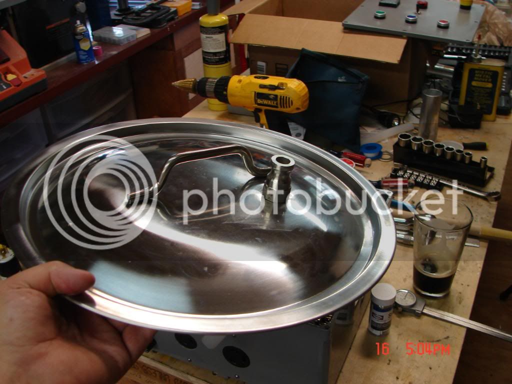
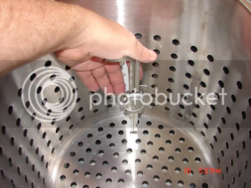
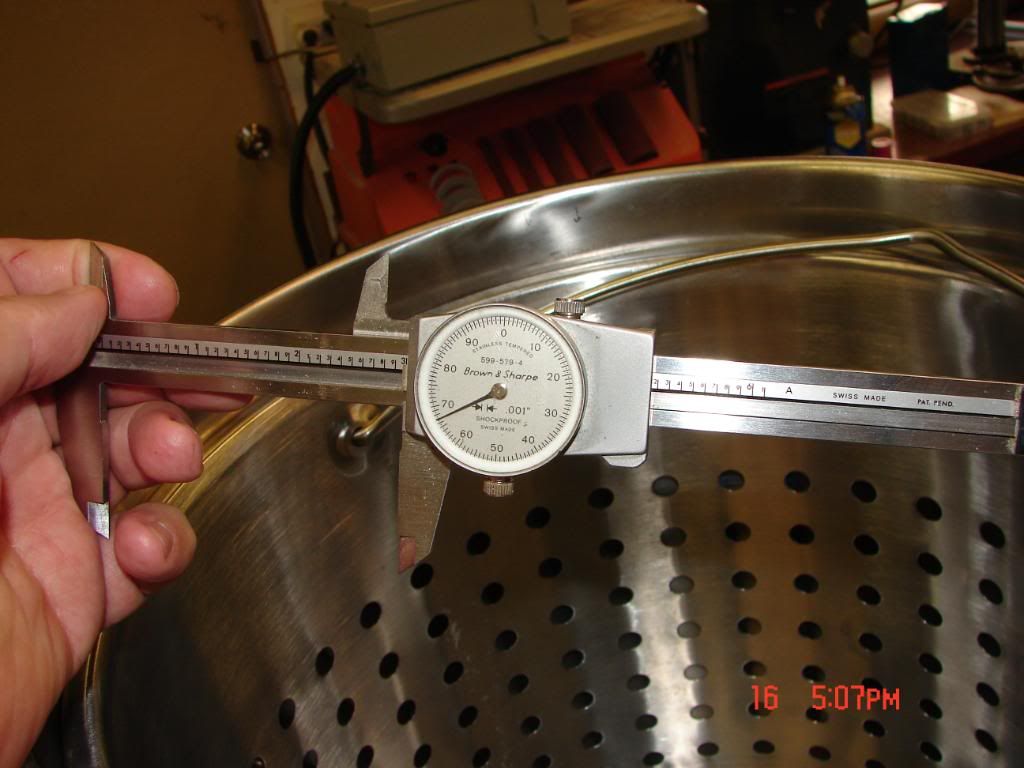
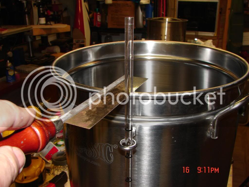
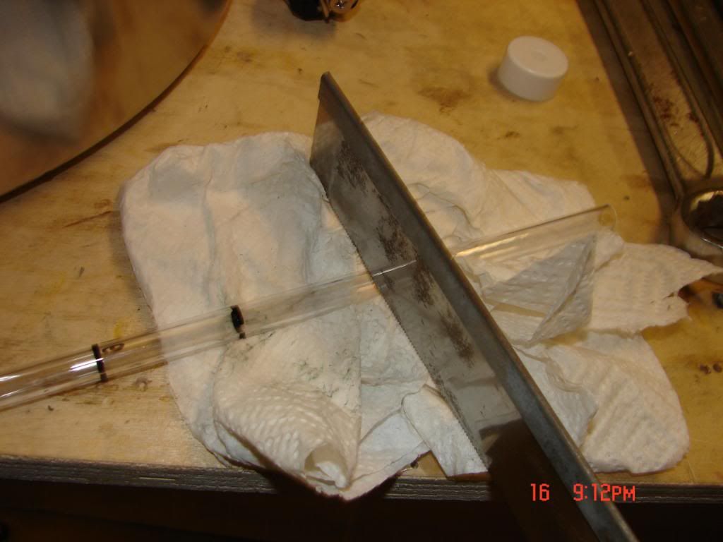
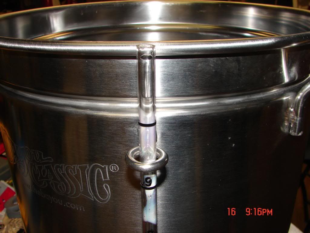
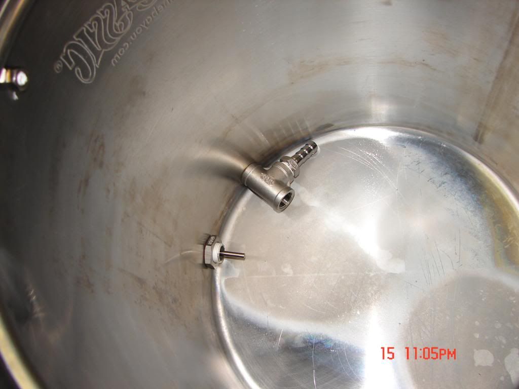
To allow greater flow during mashing I am going modify my steamer basket using the thughes method.
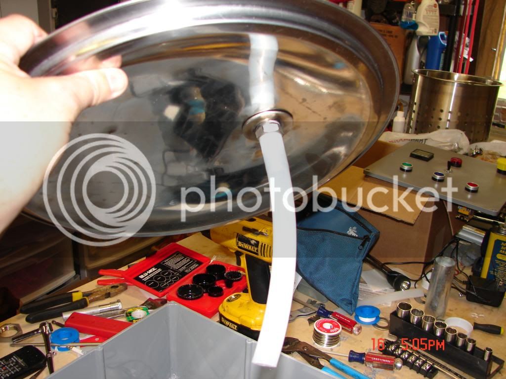
johnodon's whirlpool apparatus is just to easy and effective to pass up.
Members like P-J who spend their valuable time developing all sorts of wiring schematics for laymen like me are invaluable.
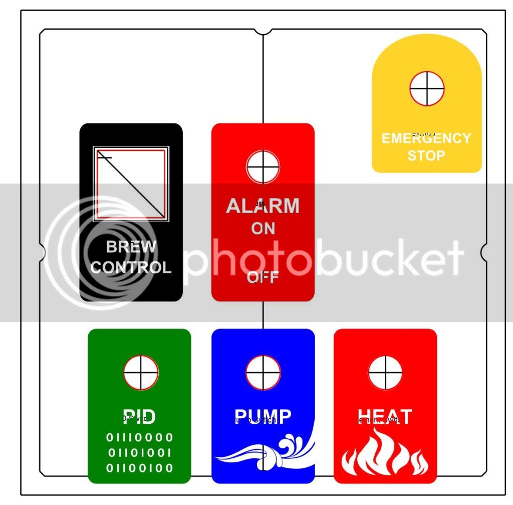
This is the P-J wiring schematic that I will use except with a 4500w element.
Auberin-wiring1-a4-5500w-BIAB-30d6-s.jpg

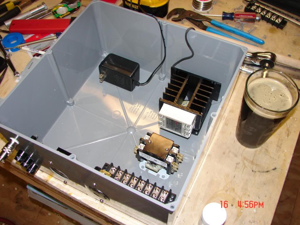
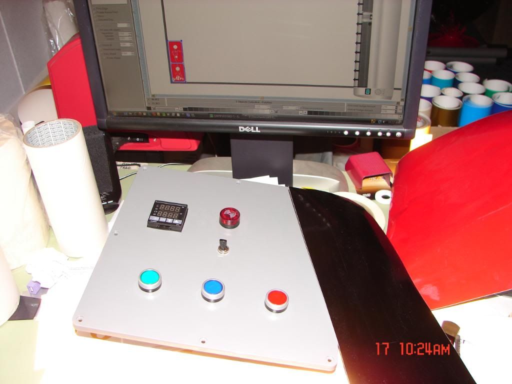
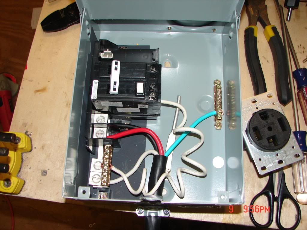
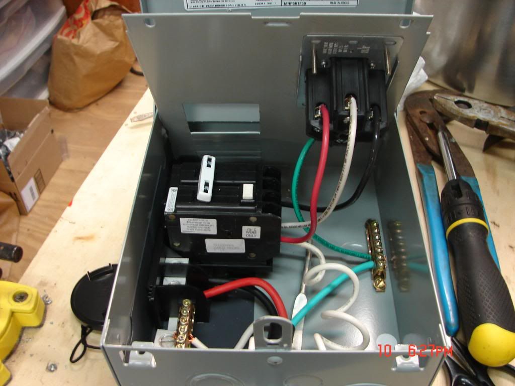
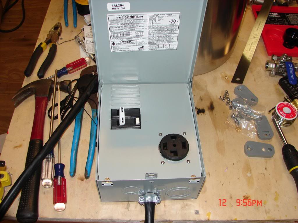
This is the Spa box and wiring diagram I used.
power-panel-5a.jpg
 
The only additions that aren't covered in the schematic is a 240v red Auber LED lamp on the gang box to indicate when the element is getting power and a heavy toggle switch to turn the alarm on and off.
 
Wiring extension cord to spa panel.

DSC00107.jpg


Outlet wiring and attachment. Note: 10 gauge wire was used to complete the connections.

DSC00105.jpg


Finished

DSC00108.jpg
 
Subscribed. Looks like you are off to a great start. I'm looking forward to seeing how this turns out. Take lots of pictures!! FWI, the Auber linkes don't work.

I'm inspired :rockin:
 
Subscribed. Looks like you are off to a great start. I'm looking forward to seeing how this turns out. Take lots of pictures!! FWI, the Auber linkes don't work.

I'm inspired :rockin:

Fixed all the links. I will be taking plenty of pictures. :mug:
 
Did a little work on the kettle.
Using the slug buster to make the holes for fittings.
biab2.jpg


Pulling cutting head through.
biab3.jpg


Perfect hole.

biab4.jpg


Spigot and sight glass done.

DSC00089-1.jpg


DSC00090-1.jpg


Inside, the 1/2" barb should work as a pick up. If it doesn't do well I will try something different. Haven't installed the magnesium rod yet. Element will be here tomorrow.

DSC00091-2.jpg
 
This Carlson junction box from Home Depot is the perfect size for my purpose. Very roomy! Cuts and drills like butter.
Got the control panel front layout done and ready.

biab12.jpg


Pilot holes drilled.

biab14.jpg


Drilling holes.

DSC00092-1.jpg


Test fitting.

DSC00091-1.jpg
 
Getting layout lines for the PID access.

DSC00095.jpg


Lines ready and 1st 3/8" hole drilled.
(Not shown) I continued around the inside of the boundary with the drill until I had completed a circuit. Finished with razor knife and file.

DSC00098-1.jpg


The plastic injection point made a perfect spot of the alarm on/off switch. Needed a little flattening on the back side.

DSC00094.jpg


How about that?

DSC00090.jpg

DSC00105-1.jpg
 
I spaced the components out as best I could so I can get to them while wiring. There looks to be room for expansion some day.
The front of the control panel doesn't look like much yet but I am going to make some vinyl decals to spruce it up a bit.
 
A few gadgets.

DSC00100a.jpg


Checking prospective positions. I changed my mind from the original plugs and outlets I had. I went with twist locks instead because of the placement of the outlets.

DSC00101.jpg


Sizing the outlets.

DSC00104.jpg


Wow that went quick.

DSC00107-1.jpg
 
Finally found a use for that Masscool fan I bought a few years ago. I will power it with an old 12v wallwart. The SSR isn't permanently mounted yet, I will add some Arctic Silver I had left over from a computer build when I do the final install.

DSC00108-1.jpg


Mounting the fan to the heatsink.

DSC00109.jpg
 
Great build!

What is a slug buster and where can I get one? It looks like it easily went through stainless.
 
Where did you get that box?

Thanks guys. I am surprised how fast this goes once you get going. Remember, plan, plan, plan, then cut and drill.


The box came from Home Depot, Carlon 12 in. x 12in. x 6 in. Junction Box, $33.60. The photo and the title are wrong on the website. The price and the description/specifications are correct. When using a high speed tools the plastic tends to melt so keep that in mind when cutting and drilling this box. If you have a hole that isn't quite the right diameter you can use a razor knife or a dowel wrapped with sandpaper to enlarge it just a bit. You can use a Dremel with a mandrel but only on lower RPMs.
 
Great build!

What is a slug buster and where can I get one? It looks like it easily went through stainless.
A slug buster is also known as a knockout punch. I got the set from Harbor Freight. It is a cheap set but I understood what I was getting into when I bought it. What I mean is my Bayou Classic kettle is thin so I figured if this set lasts for the 4 holes I need it for it would be worth it. I wasn't going to pay $100.00 for two Greenlee punches that I might never use again. At least with the set, if they last, you have four different sizes for $25.00. The 3/4" knockout is already showing signs of fatigue with 3 holes cut. These work best if your starter hole is just slightly larger than the bolt. That way the cutter is precisely centered in the hole (Very Important). I wouldn't use this punch set on anything thicker than this thin kettle because they just wont hold up. A step drill will work but you have to have a good grip on the drill and your kettle held sturdy.
Nonetheless, the punch did cut through the thin stainless with relative ease so I can recommend it for just this purpose. It might leave a bit of a burr but is easily ground off with a Dremel or any such grinder.

biab9.jpg

biab10.jpg
 
Very nice. I intend to copy a lot of this and leave room for a future countdown timer. Are you intending to install any terminal strips or will you use wire nuts to connect the wires inside your control box?

I was planning to buy a regular electrical enclosure, but this is a lot - like $80 less expensive. .

Thanks. :D I do intend to use terminal strips. I'm thinking maybe lined up vertically but not sure as of yet. I am going to have a homebrew and sit down and think about it.
My power is going to come in down near the two outlets so the terminal strip may end up down there.
I have to cut venting somewhere because of the fan on the SSR heat sink so that may come into play as well.
 
I did a little work today on the graphics for the vinyl C-Panel decals. If you are wondering, the 1's and 0's on the PID decal are binary code for those three letters. P I D = 01010000 01001001 01000100

c-Panel_DECALS.jpg
 
Subscribed. Looks like you have a majority of the same parts I have or am looking at - Same junction box and Harbor Freight punch set.

Keep up the good work.
 
Just to give you an idea how thick the box is.
.182" is typical throughout.

DSC00094.jpg


DSC00089.jpg


Ha Ha! finally found the rest of my spring tip bottle filler.

DSC00106.jpg
 
Measuring the depth from the bottom of the steam basket to the bottom of the kettle.

DSC00103.jpg


2.967" , so a touch off 3". Plenty of room for the element.

DSC00105.jpg
 
Lets cut the access for the element. I measured up 1-1/2" from the bottom and used the auto punch to get my mark.
DSC00107.jpg


Pre-drill.
DSC00108.jpg


Step drill.
DSC00110.jpg


These punches are cool tools.

DSC00115.jpg


Literally, like butter.
DSC00117.jpg
 
I'm going to solder the lock nut onto the kettle so this cleaning the metal around the hole is very important.
DSC00118.jpg


Getting a nice clean flat surface for the solder to wick up to.
DSC00119.jpg


DSC00120.jpg
 
Solder rolled up to just a hair larger diameter than the opening, don't want it dripping through. You can see the liquid flux on the kettle. The "Soldering Stainless Steel" thread is great. There is so much good information in that thread I highly recommend you read it if you haven't
DSC00121.jpg


Locknut sitting on top of the solder.
DSC00122.jpg


There was a good bit of solder there so I had a bit of runoff. No big deal, easy to clean up with Scotchbrite wheels.

DSC00124.jpg
 
Now that I reinstalled the hardware I thought I'd go ahead and trim the sight tube. Using my razor saw to mark it level with the top of the kettle.
DSC00126.jpg


Once marked I laid it on a folded paper towel to keep from scratching the tube while sawing off the excess.
DSC00127.jpg


I used the torch to smooth the edge up a bit.
DSC00128.jpg
 
Did you use propane or mapp gas? I'm about to soder everything too. I made the dimpling tool and have practiced on the lid now just need to do it to the keg.
 
Did you use propane or mapp gas? I'm about to solder everything too. I made the dimpling tool and have practiced on the lid now just need to do it to the keg.

I used propane because it doesn't get as hot as MAPP and, according to several of the guys in the "Soldering Stainless Steel" thread, you want to try and solder the parts as close to melting point as possible so you don't burn the flux off and lose solder.
It worked well for me. I actually had to add little bits of solder where the radius of the kettle falls away from the edges of the locknut. I would add the solder and an extra drop of flux. I got it on the first try so I didn't mess with it any more.
I plan on dimpling and soldering the 1/2" fittings in the future but the weldless fittings were quick and easy.
 
Had a little time this morning to devote to the vinyl graphics.
DSC00089.jpg


Now cutting the E-Stop decal.
DSC00090.jpg


The excess removed from the outside reveals the shape.
DSC00092.jpg


Using a dental pick to "weed" (remove) the small chaff.
DSC00093.jpg


The excess weeded and the backing tape applied.
DSC00094.jpg
 
The decal applied.
DSC00095.jpg


Peeling the tape backing from the decal.
DSC00096.jpg


Application done.
DSC00097.jpg


With the button installed.
DSC00099.jpg
 
Showing how the decal is lined up before application. The paper backing and application tape are still on during this process.
You use a piece of masking tape to temporarily affix the decal. Measure once, twice then press the masking tape to get a good seal. The masking tape will be a hinge.
DSC00100.jpg


After pressing the tape on fold the decal up like a door.
DSC00101.jpg


Peel the paper backing off to reveal the back (adhesive side) of the decal.
DSC00102.jpg


Now carefully fold the decal and backing tape back down. Using a finger working from center to the edges to get a good "stick"
DSC00103.jpg


Using a plastic squeegee for final application to remove air bubbles and get a permanent seal.
DSC00104.jpg


With the PID installed.
DSC00105.jpg


All finished! It turned out pretty nice. :mug:
DSC00107.jpg
 
I didn't like how the site tube fits so loose in the eyebolt so I added a grommet to center the tube.
Went and dug up a 3/8" grommet.
DSC00114.jpg


The grommet wouldn't willfully slide into the eyebolt while it was intact so I trimmed the flange off one side with a pair of scissors.
DSC00116.jpg


Trimmed up.
DSC00117.jpg


Installed.
DSC00118.jpg
 
Now time to finish the kettle. The box won't get good contact with the kettle so I will solder on a ground lug. I bent the little flange a bit so it would fit the radius of the kettle better.
DSC00119.jpg


Lug soldered on and ready.
DSC00121.jpg


Using a hole saw on the gang box to clear access for the hex head on the element.
DSC00130.jpg


Flattening the back of the box.
DSC00131.jpg


Rough sanded back side.
DSC00132.jpg


Marking the cover. Using a ruler across each corner will give you the exact center of the cover.
DSC00133.jpg

DSC00134.jpg


Like butter.
DSC00135.jpg
 
Back
Top