wiring the alarm?

Homebrew Talk - Beer, Wine, Mead, & Cider Brewing Discussion Forum

Help Support Homebrew Talk - Beer, Wine, Mead, & Cider Brewing Discussion Forum:

This site may earn a commission from merchant affiliate links, including eBay, Amazon, and others.

Bachhus

Well-Known Member
Joined
Dec 19, 2010
Messages
125
Reaction score
4
Location
Albany
So im in the process of builing my control panel for an electric setup. Any reason why I could not wire the alarm outputs of two PID's and a Timer (all Aurber) to the same input of the alarm. Then just have a single on/off switch that controls if this power can get to the alarm itself? Basically no reason to have seperate switches turing on/off the alarm for each individual PID and Timer. Any down sides of doing this I'm not seeing?

Thanks for the input.

Mark
 
No, as long as you are using the same 120V source. If your system is 240V, then if you use 120A for one PID and 120B for the other, if for some reason you get an alarm at the same time and 120A and 120B meet it wont turn out well. Even if you are using the same source you can easily use a relay or two, to prevent that.
 
No, as long as you are using the same 120V source. If your system is 240V, then if you use 120A for one PID and 120B for the other, if for some reason you get an alarm at the same time and 120A and 120B meet it wont turn out well. Even if you are using the same source you can easily use a relay or two, to prevent that.
That's not quite correct. Auber Instrument PIDs and Timers use relay contacts as the alarm output control. Even if all 3 devices go into alarm mode at the same time, it should not matter. There is no voltage present on the alarm terminals of the devices.
 
That's not quite correct. Auber Instrument PIDs and Timers use relay contacts as the alarm output control. Even if all 3 devices go into alarm mode at the same time, it should not matter. There is no voltage present on the alarm terminals of the devices.

I'm not sure if I'm following you. Lets say you have PID1 and PID2. PID1's alarm relay input is fed with 120A and PID2 alarm relay input is fed with 120B. Both alarm outputs feed to 1 alarm. Since you have 2 opposing sources feeding to one device, if they both output at the same time they will short phase to phase at the alarm. The PID's themselves will be fine, but at the alarm where 120A and B meet is where the phase short will occur. If PID1 and PID2 alarm relays are fed with the same phase power supply then nothing will happen (just how a hold-in circuit works with back feeding the same voltage supply).

Here is an example, there is very common (but incorrect) practice in terminating unused 240V lines. Lets say you hire someone to install a gas water heater and remove your electric. I'd say a solid 80% of the electricians will terminate the 120A and 120B lines together in the junction box. They do this so that if you accidentally turn on the breaker it will immediately kick off. Its the same scenario that you would have at the alarm if 120A and 120B feed at the same time to a common point it will short. You should never intentionally short something as the short can be so sudden it can damage the transformer before you breakers pop. This can be caused by a difference in the AIC rating of your breakers compared to your residential transformer. Depending on the impedance of the transformer and run of wiring to your house and your breakers AIC ratings. Most the time your residential breakers should be around 10kAIC and is plenty for the transformer, but some situations with larger transformer a higher AIC is required. Either way if your breakers AIC rating is lower than your transformer then it is possible for a over amp draw condition to hit the transformer before your breakers stop it.
 
Thanks for the input guys, i'm no electrician but I do know enough to not run different PID's on seperate 220 leads. I just wanted to make sure I wasn't missing something on having multiple inputs being run to the same alarm. All the PID's and Timmer will be powered by the same source so no issues there.

Thanks for the input
Mark
 
I'm not sure if I'm following you.
...
...
Sorry but: It is very obious that you do not.

Nor do you have an understanding of how the alarm operates on the Auber Instruments PID's & timer.

They both have internal relays. The PID SYL-2352 PID uses terminals 1 & 13 for Alarm 1 output. Inside the PID terminals 1 & 13 are the n/o points on a relay. Simply - that's all it is. There is NO power or voltage delivered to these terminals. Alarm 2 output terminals are 13 & 14. thet are aslo simply the n/o points on another relay.

Auber Instruments Timer ASL-51 uses terminals 6-7-8 for its alarm output. These Timer terminals are simply the connections to an internal relay inside the Timer. Terminal 7 is the common. Terminal 6 is the n/c contact and Terminal 8 is the n/o contact. Like the PID, there is no power, voltage or current presented to these connections.

Nuf said.
 
...
Let's say I connected terminal 13 (common) of my SYL-2352 PID to 120v phase A and I connected terminal 7 (common) of my ASL-51 Timer to 120v phase B.
...
Let's also say that I have terminals 1 of the PID and 8 of the Timer connected to the same alarm device (a bell).
...
Just a note: If you even consider doing anything like that, you have no idea what you are doing. If that's the case, I suggest that you avoid wiring electrical devices and also electric brewing.

What you are suggesting is just plain wrong.!!! If you don't know why, you are playing "You bet your life".
 
Sorry but: It is very obious that you do not.

Nor do you have an understanding of how the alarm operates on the Auber Instruments PID's & timer.

They both have internal relays. The PID SYL-2352 PID uses terminals 1 & 13 for Alarm 1 output. Inside the PID terminals 1 & 13 are the n/o points on a relay. Simply - that's all it is. There is NO power or voltage delivered to these terminals. Alarm 2 output terminals are 13 & 14. thet are aslo simply the n/o points on another relay.

Auber Instruments Timer ASL-51 uses terminals 6-7-8 for its alarm output. These Timer terminals are simply the connections to an internal relay inside the Timer. Terminal 7 is the common. Terminal 6 is the n/c contact and Terminal 8 is the n/o contact. Like the PID, there is no power, voltage or current presented to these connections.

Nuf said.

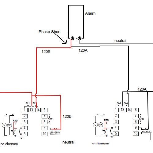
I'm not trying to argue with you here, but you still have no clue what I am saying. I know that the alarm relays are not self supplied, which is exactly what I am talking about. Ill just draw a picture here, since we aren't helping anyone by arguing.

alarm1.jpg


Hopefully you can see what I am talking about.

This picture is not the correct way to wire, just using it as an example.
 
I see very well what you are saying. If anyone wires PIDs and/or Timers in that manner, they have no business messing with electricity in any way shape or form. That wire setup will destroy both PIDs is a flash second when they both go into alarm mode.

I'm done!
 
Cool, glad we are on the same page now. I was just trying to help the OP on letting him know when its an issue to have multiple inputs to one device.
 
Back
Top