Feedback on Control Panel plans

Homebrew Talk - Beer, Wine, Mead, & Cider Brewing Discussion Forum

Help Support Homebrew Talk - Beer, Wine, Mead, & Cider Brewing Discussion Forum:

This site may earn a commission from merchant affiliate links, including eBay, Amazon, and others.

0verdrive

Well-Known Member
Joined
Mar 12, 2009
Messages
72
Reaction score
6
I'm in the planning stages for converting my brew system to electric. I'll be putting in a RIMS system, as well as electric heating elements for my HLT and BK. Ideally, I'll use a single control panel to control them all.

I based my design on Kal's tutorial, with the following changes:

  • I'd like to use a 12x16 box, rather than 16x16, if possible. This will allow me to build the control pane into my existing brewing rig.
  • In an effort to reduce cost, I won't have a timer, although my mock-up leaves room for one in case I decide to add one later
  • I want to control my MT RIMS and HLT heating elements simultaneously, and the BK heating element on its own.
  • My system is a 3-tier system, so I won't need to control extra pumps, aside from the pump for the RIMS system. Ideally, when I turn on the RIMS power, it will turn on both the pump and heating element, reducing the number of switches needed. (See explanation below)

I'll be running off a single 30A 240V (10 gauge) wire. In order to run two heating elements at once (for the HLT and RIMS) I'd like to follow the advice given in https://www.homebrewtalk.com/f170/question-about-amp-draw-243248/ where he eventually decided that he could power a 3500W heating element for the HLT and a 2000W element for the RIMS simultaneously, with a 5000W element for the BK.

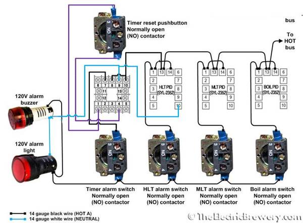
With respect to functionality, I'd like one switch that will switch between the HLT and BK, as per Kal's design. However, if the switch has the power to the HLT turned on, I'll use the HLT and RIMS switches to turn the individual elements on as needed. Additionally, I'd like the RIMS power switch to be a DPST that will turn on both the pump and the heating element simultaneously, as in the wiring diagram shown below.

I've attached a couple of mock-ups I did to give me a general look/feel of the control panel as a whole. I think the spacing will work out alright, but I'd appreciate anyone's input. The way I picture it working is to use the HLT/BK switch to determine whether power goes to the BK (solely) or to the HLT and/or RIMS. If it goes to the HLT/RIMS, I can use the associated switches to turn each on or off, as needed. This will let me heat sparge water to the desired temp while maintaining my mash temp.

Additionally, I need to come up with a wiring diagram. It's relatively close to Kal's setup, but the lack of timer and an additional RIMS controller are enough to make me want to have a clear understanding of how it should all wire up. Does anyone know what software is used to create the wiring diagrams I've seen online?

Any comments/feedback would be welcome!

Control Panel Mock-Up
ControlPanel6.jpg


Mock-Up with rough dimensions. (Relatively close to scale)
ControlPanel6_Dimensions.jpg


Wiring diagram using DPST switch to use one switch to turn on both the RIMS pump and heating element simultaneously (Found in https://www.homebrewtalk.com/f51/rims-dummies-114997/index86.html#post3159711)
31495d1312988353-rims-dummies-rimsswitch.gif
 
You seem like you know mostly what to do so I'll keep this shortish. Essentially, you are going to have 3 element circuits built just like kal except at the element on switches (and really you're gonna be similar there too) There are lots of ways to skin this cat, this is just one.

Your HLT/BK switch is going to be a 2 position toggle switch with 3 NO contact blocks on it (2 stacked on the HLT side, one on the BK side) wire from the stacked blocks right into the other 2 switches respectively and build the standard circuits from there with each on/off switch controlling the actual elements. The BK side is standard Kal style.

Also, without the timer you're losing half the functionality of the alarms. The 30 dollar Auber one works just fine, its just not as ergonomic. Plus with the Auber you aren't required to have a reset switch as one is built in (you still can if you want). If you hate the Auber you can always replace it with the Omega one later and just add a reset switch. If you search on this forum, there's a great picture of how to wire the Auber for a TEB style control.

P.S. You could get away without the 2 stacked blocks and just wire out from one block to both switches. I just like to keep circuits as separate as possible as a general practice.
 
Thanks for the feedback! While I have a decent idea of how this should all come together, some of the details are a little sketchy...

Your HLT/BK switch is going to be a 2 position toggle switch with 3 NO contact blocks on it (2 stacked on the HLT side, one on the BK side) wire from the stacked blocks right into the other 2 switches respectively and build the standard circuits from there with each on/off switch controlling the actual elements. The BK side is standard Kal style.

I was thinking that I'd have a 3-positition toggle switch, with the middle position being "off." (This would effectively turn off all heating elements, which would be the default position, hopefully reducing the likelihood of accidentally turning on a heating element.)

But I've never actually seen an industrial switch, so I'm a little confused about how the contact blocks work on the back side. It sounds like there is room for 2 contact blocks to be screwed directly to the body, while additional blocks can be "piggybacked." First, can anyone explain how you "piggyback" a contact block? How does it get mounted on the inside of the enclosure, if there isn't room to screw it to the switch body? Also, once it's mounted are we talking about just daisy-chaining the wiring, or does the operator need to be able to physically throw a switch?

I ask because while I agree with your suggestion, I'm not sure how to implement it. If I understand you correctly, you're suggesting that I have 3 blocks on the back side of my HLT/BK switch - two for the HLT and RIMS, which would both be turned on when the switch is on the "HLT" setting, and one for the BK. If there are only two contact blocks by default, I'll need to piggyback an additional contact block, and I want to ensure that I'm doing it correctly. Also, will I need to order an additional contact block, or is it likely that I'll have an extra block from one of my other switches? (Am I correct in my belief that they generally ship with two, where I'll frequently only need 1, thus providing an extra that can be used elsewhere?)

As a side-note, this makes it sound like the switches are (by default) DPST, and with each contact block that's piggybacked on, it becomes multiple pole, single-throw, correct?

Also, without the timer you're losing half the functionality of the alarms. The 30 dollar Auber one works just fine, its just not as ergonomic. Plus with the Auber you aren't required to have a reset switch as one is built in (you still can if you want). If you hate the Auber you can always replace it with the Omega one later and just add a reset switch. If you search on this forum, there's a great picture of how to wire the Auber for a TEB style control.

That's fantastic! I had somehow missed that there were alternatives to the timer, and while I would love to have one built-in, $160 seemed pretty steep. That said, I'll definitely incorporate the Auber ASL-51. I assume the diagram you're referring to is this one?

TimerWire.jpg


With respect to timer buttons, since I'm working with a smaller space than Kal, I'm trying to reduce the number of pilots to those that are absolutely necessary. It appears to me that the buzzer and pilot light are redundant, since the buzzer is also a flashing pilot light. If that's the case (correct me if I'm wrong) I really only need a buzzer. That said, I have a spot for an additional pilot light (see new mock-up below) that would be associated with the timer. If I go with the Auber timer, it will have a built-in reset button, so I don't need that - but since I don't need the pilot either, I'm leaning toward having a redundant reset button, since that will allow me to later upgrade the timer if I so desire. My question is this: is there any reason to have a timer pilot, if I have a buzzer? Otherwise, is there anything that my new mock-up is missing that would be better served than a semi-redundant reset button?

ControlPanel6_wTimer.jpg


Thanks again for your feedback - I'd much rather hash out the design before-hand than get halfway into a brew and think "man, I wish I'd done this differently!"
 
Use illuminated selector switch to provide feedback/confirmation.

I'm sorry - I'm not quite clear where you're suggesting that I use the illuminated selector switch. Are you indicating that rather than a standard "reset" button, I should use an illuminated momentary contact switch such as this one?

Thanks!
 
you're on/off hand/off/auto switches 3 position maintained LED illuminated
Like this

m_gcx326124l.jpg

BTW: that brand you linked to is crap, been there, tried that, threw them out
 
Hi

I suspect I have just missed something, but I'll ask anyway:

You start off talking about a 220V system. All the diagrams appear to be for a 110V system. Did I miss something?

Bob
 
1. Switches: You have the right idea on the switches and how the block work. Most of the Chinese switches we cheapos buy for these things come with one block only and you can add more. The second block just screws into the ass end of the other block. For most switches I have used, you can only stack 2 high. I would link to additional blocks but it seems the ebrewsupply guy's website is down right now. You can get a 10% off coupon from him still (I think, got one last week) in the vendor area. I got my electric bits and pieces in 4 days.

As far as a 3-way goes, I have used these before: http://www.omega.com/pptst/OMPBD7-SS.html I'm sure you can find cheaper but these are high quality goods. Note that they come as a switch with one contact block so you'd have to order 2 more (also not cheap). Just leave the middle slot blank as your "off" and place the block on the edge slots.

I actually used an Omega 4-way to control my friend's e-brewery where it went BCS - OFF - HLT Manual - BK Manual. It's a pain to figure out and Omega doesn't stock the 88 cent piece of plastic you need to make the switch work right, but in the end it is pretty cool and he liked it a lot.

I do agree on the lighted switches hoppy mentioned, they are nice. You'll spend about 5$ more per than a switch/light combo but it's worth it.

2. Alarm: That's the diagram alright. The reset button would only be worth it if you saw yourself upgrading to the Omega. I don't think it's worth the $130 to be able to change each number with a separate button. But, to each his own.

3. Buzzer: Agreed, I have a flashey/buzzy one on mine too with no indicator.

As a total aside it's great that you're working on understanding your own rig before wiring it all together. Planning now will make it go a lot smoother.
 
Hi

Consider that there will *always* be more stuff to control than you now have. How ever many gangs the switch has, you ultimately will have one more valve, light, buzzer, pump, or roto rooter to run than you have gangs to switch.

Another way to do all this (really only for thought):

Run the "stuff" off of relays. Power the relays with something reasonable like 12 or 24 volts DC. Switch the relays on by pulling the coil to ground through a diode. Diodes are dirt cheap. Relays don't cost much more than these fancy switches and often cost less. Run the diodes to switches you can re-label. Since the switches are doing low voltage / low current they are cheap and easy to find. You don't need multiple decks, everything switches to ground.

Again - just to think about before you commit to this.

Bob
 
Hi

I suspect I have just missed something, but I'll ask anyway:

You start off talking about a 220V system. All the diagrams appear to be for a 110V system. Did I miss something?

Bob

I am planning a 220V system, but am figuring out how the wiring will work based on portions of various wiring diagrams I've found in similar posts. I'm currently working on a wiring diagram for my own setup, which I'll post for review when I'm done.

That said, the RIMS heater diagram shown above is intended to indicate how I'd like a DPST switch to turn on both a pump and heating element with a single switch. However, in my case, I intend for the hot line for the heating element to go through an SSR to jump to 220V.

The wiring diagram for the Auberin ASL-51 timer (I believe) is 120V - the only 220V section should be through SSRs powering the heating elements.

(At least that's how I picture it working - please let me know if this doesn't make sense.)
 
1. Switches: You have the right idea on the switches and how the block work. Most of the Chinese switches we cheapos buy for these things come with one block only and you can add more. The second block just screws into the ass end of the other block. For most switches I have used, you can only stack 2 high. I would link to additional blocks but it seems the ebrewsupply guy's website is down right now. You can get a 10% off coupon from him still (I think, got one last week) in the vendor area. I got my electric bits and pieces in 4 days.

Thanks for the feedback, and for the nod to the discount at ebrewsupply! I pm'd him - we'll see if he still has discounts to give away.

As far as a 3-way goes, I have used these before: http://www.omega.com/pptst/OMPBD7-SS.html I'm sure you can find cheaper but these are high quality goods. Note that they come as a switch with one contact block so you'd have to order 2 more (also not cheap). Just leave the middle slot blank as your "off" and place the block on the edge slots.

Good to know which parts are quality. Unfortunately, I'm pushing my budget as it is, so I feel like I need to go with cheaper parts where I can. That said, if they're so cheap that they need to be replaced eventually, I ought to be able to swap them out easily enough (correct?)

I do agree on the lighted switches hoppy mentioned, they are nice. You'll spend about 5$ more per than a switch/light combo but it's worth it.

I'm afraid I don't quite see the point in the lighted switches. With the mock-up I have above, I'll have a pilot light that turns on when a device has power. The lighted switch will just (presumably) light up when it's providing power to something, but won't indicate to what, correct? So wouldn't the pilot lights provide more information, and thus be the way to go? I'm not trying to be argumentative - I just want to understand why you recommend lighted switches (ie: what advantages they have) before I make a decision.

3. Buzzer: Agreed, I have a flashey/buzzy one on mine too with no indicator.

Good to know - I thought having a pilot light and a flashey buzzer seemed redundant, but wanted to make sure before accidentally designing myself into a corner and thinking better of it too late...
 
You have 3 selector switches HLT PWR / RIMS PWR, HLT BK if I interpret your drawing correctly.
The switch labels you chose are more descriptive than the pilot light labels making the pilot lights redundant if lighted switches are used.
Also, why use a selector switch if a simple on/off pushbutton will suffice?
What is the purpose of the alarm switches?

I see what you're saying - thanks for the follow-up explanation! I'll have to consider which route I want to go.

As for the alarm switches, (the way I understand it) I need to be able to tell each PID whether to turn on an alarm when a target temp is hit, etc. (I then need to be able to turn it back off once I'm done with it.) That said, I could use either a selector switch or a (maintained contact) pushbutton switch. I'm just using selector switches, because they seem fairly easy to come by, and that's what was used in Kal's TEB tutorial. Are there advantages to using one over the other?
 
Using a 3-position selector switch you could eliminate the alarm switch. e.g. Hand/Off/Auto
Making only one switch necessary. Then again, if you are wanting to just silence an alarm, a simple momentary pushbutton is more than capable of handling that job.
Question, why sound an alarm when target temperature is hit? To me, it's seems more logical to have an indicator showing the heater on. (my opinion)

582636_223666351071042_65206560_n.jpg


Pushbuttons are less expensive if all you want is on/off. They are available from many suppliers. We use Automation Direct for our electrical supplies.
 
I am planning a 220V system, but am figuring out how the wiring will work based on portions of various wiring diagrams I've found in similar posts. I'm currently working on a wiring diagram for my own setup, which I'll post for review when I'm done.

That said, the RIMS heater diagram shown above is intended to indicate how I'd like a DPST switch to turn on both a pump and heating element with a single switch. However, in my case, I intend for the hot line for the heating element to go through an SSR to jump to 220V.

The wiring diagram for the Auberin ASL-51 timer (I believe) is 120V - the only 220V section should be through SSRs powering the heating elements.

(At least that's how I picture it working - please let me know if this doesn't make sense.)

Hi

Ok, with some stuff on 110 and other stuff on 220, you will need more switch contacts. You can't switch a 110 V load and a 220 V load with the same contact. I mention it because people normally order switches first and then work out the rest of the wiring later. Often that means you run out of contacts and now have two switches doing the same thing.

Bob
 
Wouldn't relays for 220V be a better solution? No need for different wire or contact sizes and it conforms with standard engineering practices.
 
Wouldn't relays for 220V be a better solution? No need for different wire or contact sizes and it conforms with standard engineering practices.

Hi

That's indeed where I'm going with this. The low voltage / diode switching is the answer to a lot of issues. Simple switches and a lot of isolation. Both good things. Relays are cheap compared to all the rest of this stuff.

Bob
 
Thanks again for everyone's help! After several modifications, I'm a little closer to having a more solid plan for how everything should work. I've attached the updated mock-up below, as well as a wiring diagram I made in TinyCAD.

I can see the benefits to using lighted switches, but I'm pushing my budget as it is, so I elected to stick with standard (cheapo) switches. If/when they wear out, better switches should be a drop-in replacement, (and I should be able to afford to replace them one or two at a time.)

I also changed my approach to turning on my RIMS system. The HLT/BK 3-pos switch will still turn on the HLT and/or RIMS system simultaneously, or alternatively power (solely) the BK element. But when I have the HLT/RIMS powered, I now have a second 3-position switch that will allow me to turn the RIMS system off, power just the pump, or power the pump and heating element simultaneously. This will allow me to start the pump and verify flow (no stuck mash!) before turning on the heating element. Hopefully this will help to ensure that I don't scorch my wort.

Finally, I added the ASL-51 timer, and wired it according to the diagram shown earlier in this thread. (I don't have an external reset button, since the timer has one, so I didn't wire that section)

That said, does anyone have any questions/suggestions/comments about the following design?

ControlPanelFinal.jpg


Wiring diagram
Wiring.png


The resized version of the wiring diagram is too small to read, and the original size (which you may be able to see by clicking on the image?) is huge. A more usable size can be found here. For the most part, I followed Kal's design, so I should be relatively good to go. The areas that I modified are the switches, so any feedback on those would be great. I also added the RIMS heating element section, so I'd appreciate feedback on it as well.

Thanks again!
 
Hi

All of your loads except for one are running with relays. You already have low voltage power supplies in the design. You would do *much* better to spend another $5 on a relay to drive the pump and then do all low voltage switching. Simply route switching to the relays rather than switch main power. It's much safer, much cheaper, and more reliable.

Bob

So you're saying to use the same hardware (switches, etc) but to route low DC voltage across them, triggering relays to power the devices?

1) Am I correct in assuming that if a switch is capable of handling 120V AC that it can also be used for low voltage DC? (It's just completing a connection, so dropping the voltage should be fine, correct?)

2) I assume this is safer since if there's a short, it's a lower voltage that's shorting out?

3) Out of curiosity, why is it more reliable?

Thanks for your feedback!
 
Hi

All of your loads except for one are running with relays. You already have low voltage power supplies in the design. You would do *much* better to spend another $5 on a relay to drive the pump and then do all low voltage switching. Simply route switching to the relays rather than switch main power. It's much safer, much cheaper, and more reliable.

Bob

Another follow-up question: If I were to take your advice and switch low-voltage DC to relays, I'd need different mechanical relays, which could be switched on/off with DC, rather than 120V AC. If so, would this relay work? http://www.ebay.com/itm/8-pins-Plug-in-Type-12V-DC-Coil-30A-250V-AC-Power-Relay-JQX-30F-/230799920781?pt=LH_DefaultDomain_0&hash=item35bcbf4e8d#ht_2118wt_1163

Do you see any other areas where I'd need to use different parts? (Would I need different SSRs? Anything else?)

Thanks!
 
So you're saying to use the same hardware (switches, etc) but to route low DC voltage across them, triggering relays to power the devices?

Yes, or use even cheaper switches.

1) Am I correct in assuming that if a switch is capable of handling 120V AC that it can also be used for low voltage DC? (It's just completing a connection, so dropping the voltage should be fine, correct?)

Generaly a good bet.

2) I assume this is safer since if there's a short, it's a lower voltage that's shorting out?

If you have water in the area, getting a leakage path to 12 volts is a lot less likely to kill you than a path to 220v

3) Out of curiosity, why is it more reliable?

1) Simpiler switches, and fewer of them. They usually are what fails (often by getting hit with something).

2) The switches are coded to the task. "flip this to sparge". Fewer switches to throw each time = less chance to mess up.

3) Less high voltage running around = less chance of a *real* disaster.

4) Errors at low voltage are generaly recoverable, errors at 220V usualy damage stuff.

A stupid example:

You have five "states" a system will operate in (for instance). There are ten things in the system (valves, pumps, heaters). For a direct controll box ten things need ten independant switches. For a low voltage relay / diode system you need one 5 position rotary switch.

No it's never that cut and dried in reality, but that's the idea.

Bob
 
Back
Top