E keggle build

Homebrew Talk - Beer, Wine, Mead, & Cider Brewing Discussion Forum

Help Support Homebrew Talk - Beer, Wine, Mead, & Cider Brewing Discussion Forum:

This site may earn a commission from merchant affiliate links, including eBay, Amazon, and others.

emyers

Well-Known Member
Joined
Mar 5, 2012
Messages
382
Reaction score
28
Location
Waldorf
I started working on my new rig today. My plans are going automated but this will be a manual electric rig first and slowly go automated as it drains my wallet. So far i have 3 15.5 sanke kegs, SSR's, 2x 5500w camco elements, 2x 3500w camco elements, 1" locknuts for elements, 120v fan for cooling project box with relays. I have 2" tri clover adapters and 1/2" ss valves on there way from brewershardware, hopefully they come next week.

Today i cut the bottom off one of the pots, this will probably be the HLT because it has the smaller of the 2 lids i have, the larger lid will go on the mash tun for easier cleaning. I made a simple rig with a 2x2, carriage bolt, and hose clamp to cut the perfect circle on the bottom, I cleaned up the hole with a 60 grit flap disc on my angle grinder.

Elements will be 5500W and 3500W in each kettle. This will allow the boil to be maintained with 100% duty cycle on just the 3500W and the 5500W along with the 3500W for faster temp ramping of the HLT and boil kettle. Initially i will have DPDT switches controlling SSR's to swap between which element gets power, later a brew controller. To protect the elements i will have float switches just above the elements hard wired to the SSR's ground leg. I only have 60A main breaker so im limited in amperage (badly need to upgrade my 1971 breaker box). I have been using a similar 9000w setup with great results on a single sanke keg i made (for sale BTW).

My brother has a spray foam gun so plans are to coat the mash tun with 2-3" of closed cell.

This will be a gravity fed system with one pump for HERMS.

IMG_3329.jpg


BREW 001.jpg
 
Take a SERIOUS look at TheElectricBrewery.com. I built my rig from Kal's plans with a 50 Amp Back-to-Back control panel. I can run both elements at the same time. So what I do is, heat my strike water in the boil keggle and keep my HLT full of 15 gallons of Hot Liquor with my HERMS coil in it. It is not a fully automated brewery, but it is pretty darned spiffy. Take a look at my links in my signature line for details of my build.
 
By the way... good job on the bottom drain decision! I LOVE all three of my bottom drain keggles! You can make a False Bottom out of the disk you have cut out of the bottom of the Keg.
 
You are certainly close to the limits of your panel.

I think it makes sense to do what you are doing and build the vessels first, and the controller later once you have a good idea of how you want to use them.

The electric brewery is a great resource but the specifications are at the luxury end IMO.
 
Huaco, I do plan to run 2 elements at the same time , the 5500s and the 3500's be wired on there own paired circuits. So i can run the 5500 in the boil kettle while the 3500 is still maintaining sparge water. Thanks a ton for telling me about using the tops as false bottoms! you just saved me a bunch of $$ i don't have for over $100 in false bottoms. Now i can brew once i get the tri clovers in!

alien, I do plan to upgrade my panel. My brother will be heading over in the next few months to upgrade the panel and rewire some of the house and put legit workshop outlets in the garage, not 2 small 15A outlet's. The main line in i have can handle 120A (0/2ga?? i think) so I'm not limited on that aspect.

theElectricbrewery is nice, great source of info... but with a bcs controller i can just have an IPad and control much more valves, fermentation temps, hop dumper, and pumps then just PID's for temps. I would really like it automated enough to i can load the grain and hops, press a button and walk away. Again this is stage 1 beta, so i have a long way to go for that.

So next on my list,
-Build keg racks with angle iron that will be lag bolted to the wall, this will let me adjust height easily.
-Cut the remaining lids off
-Strip glue off kettles and start the polish process
-Find out why Brewershardware hasn't sent me a shipping notification!!!!!!
 
Just an example of what I did. I used a cutoff disk with and angle grinder and (2) #40 drills. VERY good quality drills will last. The cheap drills from the box stores will get shredded in a heartbeat. LOTS OF GOOD CUTTING OIL AS WELL.
BTW, There are over 1,200 holes in there. (yes, I counted...)
attachment.php
 
I was thinking just make slices with a plasma cutter, they should be thin enough to hold the grain bed in, whatever does get through will just get recirculated. For my initial brew i will prolly manually recirculate using my 40qt 3000w kettle to adjust temps and filter sediment. And for insulation i will just wrap a spare comforter around the mash tun.
 
Parts on order from brewhardware.com more building pics next week.
 
fittings, sight gauges, and full size false bottom came in today, updated pics in OP. I plan to use one of the cut out lids with holes as a hop blocker in the boil kettle.

I have all three kegs cut open and sized for lids. I even made a DIY how-too thread for it.

https://www.homebrewtalk.com/f51/how-cut-circle-out-bottom-keg-402136/

Should start drilling for the sight gauges and elements this week hopefully. Need to build my stands too.
 
Hmmm..... anyone know why the hell i ordered 3 sight gauges? oops... I mean i guess i can run one on the mash tun but why??
 
Don't you love realizing you got a bit click-happy? I have four male polysulfone QD's I have no idea what to do with. D'oh!
 
Boil kettle drilling and mounting complete. For the element mounts I used a small step drill to start then a carbide on a 1/4 electric die grinder to open it up. Got a hot piece of metal stuck to my lower eyelid even with safety glasses.. yea that sucked.

The elements will be getting 1"-1"npt PVC adapters filled with JB weld as housings. I have a yeast starter going now, hopefully i can do a half assed brew with the new rig next week. It will definitely be a ghetto brew rig configuration for that brew, tiered on my workbench and toolbox with 4x4's and 2x4's holding the kegs up for the valves.

I plan to put the gallon markers up the next time i have free time, hopefully tomorrow.

015.jpg


013.jpg
 
Last night I realized using any sort of hop blocker on the bottom will be a PITA with the elements. So I ordered a 18"x32" coarse nylon mesh bag to make a hop spider. Should make cleanup easier too.
 
Ordered stage one of my control box today. Two 3 way switches to swap the elements between the kettles, 4 LED's to show when the elements are on, one LED master switch, and a mushroom E stop. I also got two SS float switches for element safety switches. They will be wired in series on the control side of the SSR's. The switches will open the circuit when water goes below the element level. I also plan to run a stir motor on the HLT going off the element control circuit to prevent temperature layering.

I just finished my HLT element and sight gauge mounting. I didn't split the 5500w into a V like in the boil kettle because heat density and cleaning isn't an issue with just water. To clear the elements i bent the 5500w at the first bend by hand over the keg rim as a bending surface.

Why you should always wear goggles when grinding and not glasses.

brew rig build 001.jpg


IMG_20130422_075649_204.jpg


brew rig build 002.jpg
 
I made my connectors for the elements today. I used 1" knockouts and 1" female pvc to 1" female NPT adapters. The NPT is tapered so the knockouts wouldnt thread in more than 2 threads. A few seconds on the torch melted the pvc threads a bit to thread fully. I dont plan to move my kettle or HLT so everything will be hard wired, the other side of these wires will go right to the SSR's. Now to find some 10-3 for the 5500w side.

brew 010.jpg


brew 012.jpg


brew 017.jpg


brew 018.jpg


brew 026.jpg
 
I also made a hop spider with a paint can and 5 gal strainer. Total cost around $10. Its not stainless but its all galvanized. I forgot to grab a hose clamp so i'll give zip ties a shot for now. I discovered a can opener opens up the bottom of a paint bucket from HD perfectly. There weren't even any sharp edges to clean up. Chump/lemons BMW 2002 race car in progress in background :)

brew 005.jpg


spider 002.jpg
 
Stage one of my wiring diagram. Plan to go automated in the future but this should be more than enough to get me brewing manually. The float switches are element run dry fail safes. This diagram only shows the control side of the relays. Each element will have its black leg controlled by a SSR. There will also be a LED on the 240V side of each element to indicate if the element is energized.

Wiring stage 1.png
 
I got my hands on some 10-3 today, Its bright Fing yellow but it was free so who cares. I should be wiring up the 5500w side tomorrow. Hopefully the switches and lights come in soon so i can build my control board. For mounting im considering KISS and just mounting 2 2x4's horizontally from stud to stud, one at the top of the keg and one near the bottom. Then just use a carriage bolts through the top and bottom lips for mounting. The mash tun i will need to build a rack or tippy mabob for dumping into a wheel barrel. Hopefully this rig will be operational soon!!!!
 
Bright fing yellow lol. I jumped the gun and wired up the boil kettle with outlet plugs... Only to find out my 3 way switches and lights will be in tomorrow.

I just realized the float switches off Ebay are not just made in china... they are shipped from china!! Looks like ill have to wire them in later and just pay attention to water levels with elements.

I need to make a HD run and get two SS bolts and nuts for the ground stud. I will weld the bolts heads onto the kettle between the elements then wire the grounds onto the stud.

IMG_3629.jpg
 
The switches came in today. I went to HD and got some plywood and wood screws to build a control box out of. The bottom two relays will be for the HLT stir motor and the HERMS pump. The stir motor control will be the element safety float on the HLT; So whenever there is water, it will be stirring. The power supply is from a desktop computer, it's good for 13A @12v.

IMG_3638.jpg
 
Sweet print i picked out from mall of america in a layover for $40. 31/100. The ink is actually pearl/metallic. Dont be jealous ;) Resides over my 4 tap kegerator.

017.jpg
 
HLT and mash tun mounted. I went with 3" lag bolts into to the studs. I hung off the HLT and it didn't budge. I weigh 175 lbs so i should be good. The mash tun is on 1/2" long slots with large openings for the heads to pull out. This way i can remove it from the wall and dump the grain somewhat easily. I really want to mount it on hinges for easy dumping into a wheel barrel. This confirms my measurements, to be all gravity fed (besides the HERMS pump) i will need to place the HLT into the attic for enough vertical drop to make room for the CFC and fermenter. Once i get the digital controller i will measure the gal/min of tap water into the HLT then have the time/gal be the volume for measurements into the HLT. Until then i will be mashing out into buckets then raise them up to the boil kettle by hand. I will do a few batches like that until i can afford a SS chugger pump and the SS HERMS coil.

brew rig 005.jpg
 
Just realized manual stirring the HLT will be a chore. Got a 2' x 3/8" SS rod from amazon for only $13! Ill use the keg cut outs to make a prop and a cheapo hand drill with the trigger hose clamped to spin it.
 
Umm you wall-mounted your keggles...?

Originality - A+
Functionality - TBD

Wild stuff! Cant wait to see how this comes together.
 
Thanks I was thinking what's the simplest bracket and that's what I came up with :)

My good friend hooked me up with the perfect box. I got the control side wired in and I just tested it and it works! The power switch does not light up though. I think I'll replace it with a keyed switch and use the light up switch to control the HERMS pump directly its rates to 10 A I think.

IMG_20130428_215407_996.jpg


IMG_20130428_215357_874.jpg
 
My HLT overflow protect switch came in today. Jr says it passes QC. I wish my element protect switches were in.

IMG_20130429_171410_323.jpg
 
Finished all the wiring last night. Should be doing a test tonight and brew tomorrow!
 
ITS ALIVEEEE!!!!!

I tested it out with 3 gals in each, switches between elements perfectly. The box worked but its real tight in there especially with the large computer power supply. It will work but its real tight especially with my rats nest wiring. This should hold me over until i have additional funds to go automated and get a proper large box.

Brew tomorrow with a 33 lbs grain bill :). I'll have to lift the wort up to the boil kettle since i have no pump, the drop is not enough for my tiny CFC. I badly need to upgrade to a CFC with a 1/2 copper coil.

my 2' 3/8" SS rod came in today.. well it was supposed to.. instead i got an empty box with a 3/8 hole in the bottom. Luckily its amazon so ill have it replaced no problem. This will be the stir rod for my HLT. Ill be making a SS prop with the keg cutouts.

032.jpg


033.jpg


034.jpg
 
anyone know why the master switch wont work? It turns the system on but wont light up. I have one of the legs that supplies the power supply running 240v hooked up to it. That should be pushing 120v thru it no?
 
I fixed the master switch, ran the wire thru the light circuit so it lights up when on.
 
Finally got to brewing yesterday. My manual mash recirc sucked dumping three gals into a 3000w turkey fry pot to adjust temp.

I ran into an issue. My 5500w SSRs stay on when turned off. Its only after they have been on for a bit. Any ideas why this is happening?
 
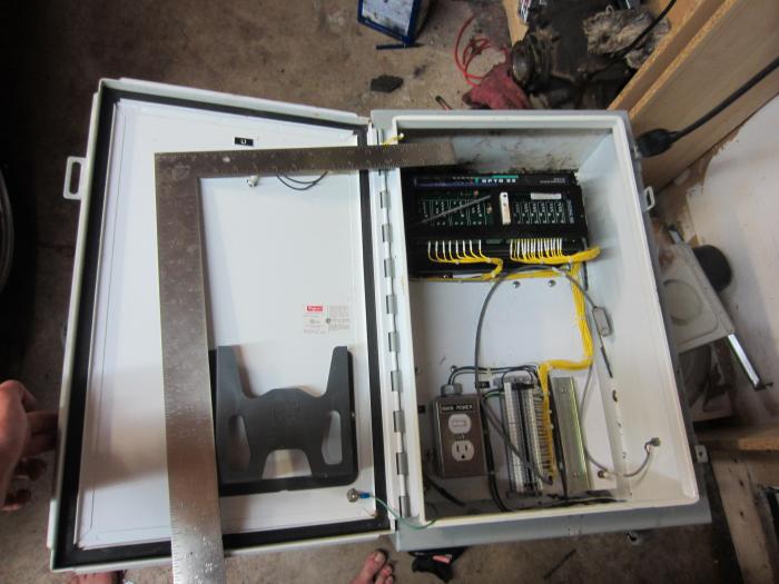
I got my hands on a nice big waterproof box to upgrade to. This should be big enough to run everything i would ever dream to expand to. Its 24"x 18" and like 10" deep. It has a few holes but i can easily make use of them, nothing excessive. Best of all it has some hardware i can use. I'm not sure what the control box is for, but im sure its not a brew controller.

BTW i still have not figured out why the SSRs that control the 5500w elements stay when they have been on for a while. The 3500w are wired the same exact way and dont have an issue.The SSR's are rated at 40A so its not like im over powering it either. I can swap between the two as designed when only doing so for a few seconds. Once the elements have been on for a min or two it seems to freeze the SSR in the on position and allows me to turn on two 5500w elements at the same time.... on the same 30A leg :O Does anyone have any recommendations to help?

IMG_3877.jpg


IMG_3878.jpg
 
BTW i still have not figured out why the SSRs that control the 5500w elements stay when they have been on for a while. The 3500w are wired the same exact way and dont have an issue.The SSR's are rated at 40A so its not like im over powering it either. I can swap between the two as designed when only doing so for a few seconds. Once the elements have been on for a min or two it seems to freeze the SSR in the on position and allows me to turn on two 5500w elements at the same time.... on the same 30A leg :O Does anyone have any recommendations to help?

When one of the SSRs is locked "on," have you checked the control voltage from the PID to the SSR? If the PID is sending the voltage signal, then there is something wrong on the PID side. If not, then it's on the SSR side. It could be PID settings, a bad PID, a bad SSR, or improper wiring.
 
Back
Top