Jester
Senior Member
I can't wait to build one of these!!!! I'm sure I will be posting some more questions once I start to wire everything up.

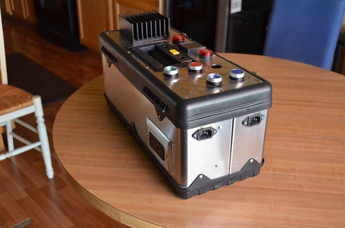
Same here - just felt more sturdy while carrying with the wood base.
Wow, very cool - way to take it to the next level!
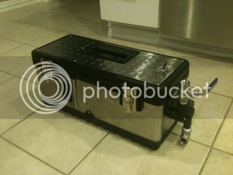
Honestly, I think the hardest part of the whole build was removing that big-ass sticker from the front. Its like they used the strongest adhesive available to put it on.
What did you use to cut though the stainless?
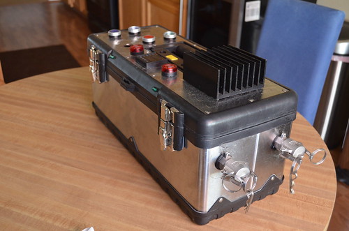
I love using it! I also use it for sous-vide.Awesome A4J! I love the toolbox control panel. You will love using it.

Wow, very cool - way to take it to the next level!
Honestly, I think the hardest part of the whole build was removing that big-ass sticker from the front. Its like they used the strongest adhesive available to put it on.
nope, sorry, but if you're really interested, I can pull most of it apart and sort of re-create the build. I still have a couple of wires to hook up (mainly the alarm).A4J, there a build thread for that thing? Love that idea, planning something similar.
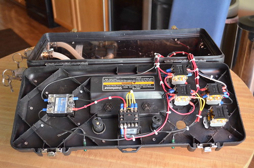
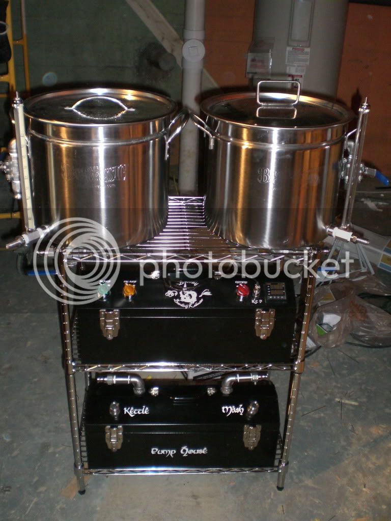
Those look very nice. I built something similar last summer. Pump, PID, and SSR all integrated to control a RIMS (which I've since gotten rid of) or a HERMS (what I currently use)

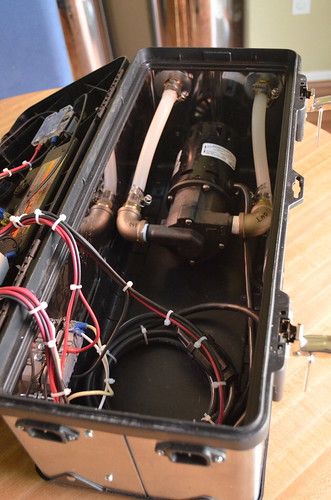
do you have any problems getting the pump to prime?


Very cool, "Basturd". I'm so happy that this idea has caught on and people have run with it. when I first posted it I didn't think that is really gonna be that great of a thing to do, but it looks like you guys have embraced it, thanks for the great ideas and variations! Cheap and useful - that's what home brewing is all about, right?

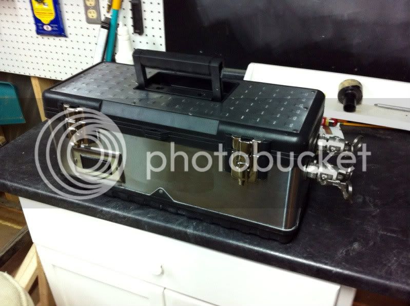
Wiring it this way I have a protected box with switches for main power (outlets controlled too) and a seperate switch for the pump. I can control the pump independently from the outlets just in case I have something else plugged in there that I want to keep running.
Maybe I'm missing something but wouldn't you need to power the GFCI outlet in order to power the pump? If the switch to the outlet is off then there is not power to pump. Also, is there any concern with the switch not being GFCI protected?
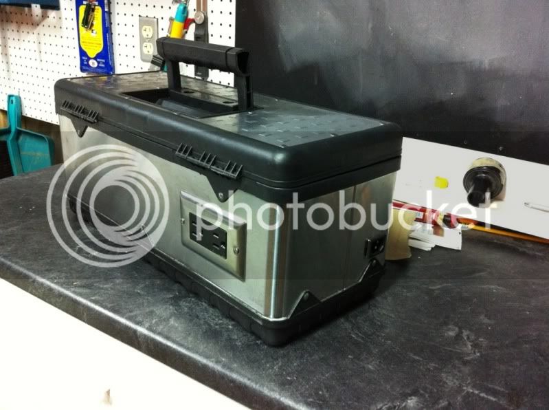
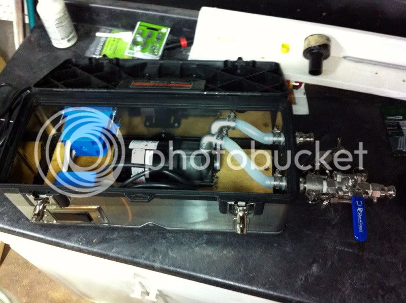
I do not use a ball valve on the pump outlet. Only one ball valve is needed in series to restrict the flow.
My pump box is on the bottom. I use the ball valves on the kettle returns to throttle the flow. Less parts, simpler layout. During hose changes, I just pinch the tubing while making the change to maintain my prime. Both ways work just fine.


Enter your email address to join: