DIY PID controller - beginner Arduino project

Homebrew Talk - Beer, Wine, Mead, & Cider Brewing Discussion Forum

Help Support Homebrew Talk - Beer, Wine, Mead, & Cider Brewing Discussion Forum:

This site may earn a commission from merchant affiliate links, including eBay, Amazon, and others.

chuckjaxfl

Well-Known Member
Joined
Feb 16, 2010
Messages
331
Reaction score
23
Location
Jacksonville, FL
I am abandoning the DIY PWM project.

A few weeks ago I bought an Arduino UNO, and have really taken to it. The PWM seems like very, very low hanging fruit now.

I though the Arduino was a specific type of microcontroller, or chip, or board. I just knew that it was over my head. What I now know is that the Arduino is not really a specific product, more of a project. The best way I can relate it is to think of America Onlne in the '90s. It took the Internet, put an intuitive, EASY to use face on it, and introduced the masses. Arduino does the same thing for the microcontrollers. You can buy one, watch a few YouTube videos, read a few examples and be working in a few hours.

In my case, I started with a sensor and an LCD display. I added the PID library a few days later, and then the autotune library. I've since connected it to a simple 115 outlet and a crockpot, which I've been using to cook sous vide successfully. Since it was all working on the breadboard ok, I started drawing a little PCB for my buttons, sensor header and such, and then learned that you don't really even need the Arduino part of the Arduino anymore once you've got all the kinks worked out. You can just pull the chip from the Arduino and install that in your project, instead. Get a new $4.30 chip for your Arduino and start all over on a different project.

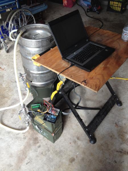
I wish I had been taking more pictures all along to show you guys. I'll post ones that I have.
 
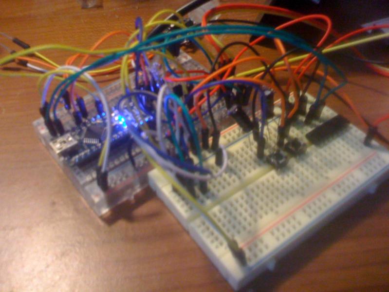
Here's the rat's nest on the breadboards. It's not as complicated as it looks.

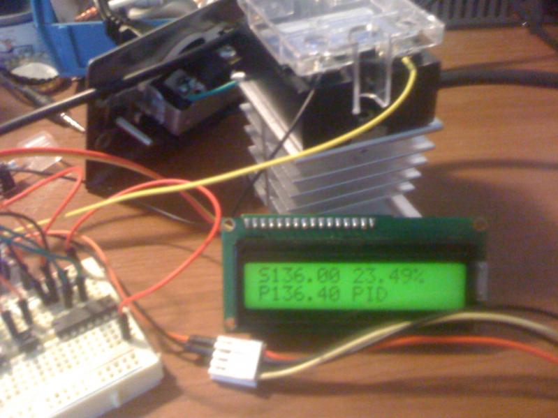
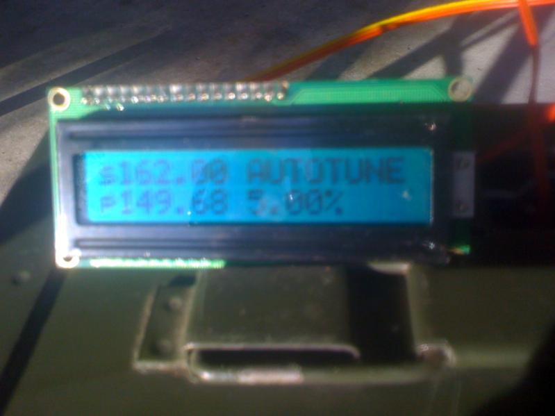
You can see the LCD, as well. In PID mode, it shows the Sv, Pv and current output %.
In manual mode, shows --- for Sv, and in ON/OFF mode, it shows --- for output %.

image-641110172.jpg


image-3879941577.jpg
 
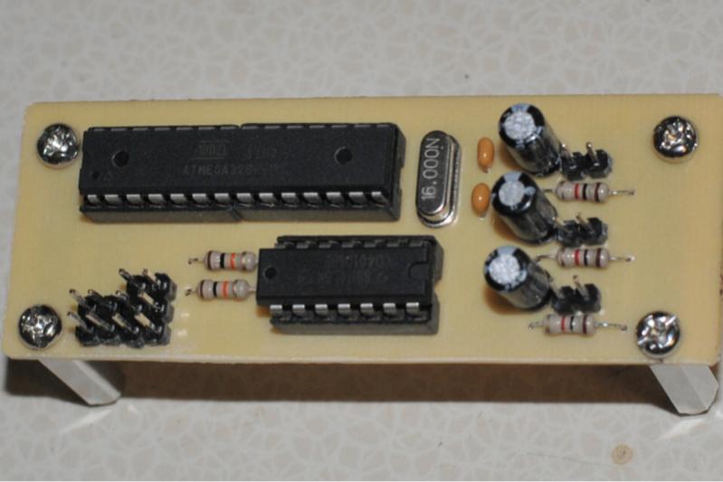
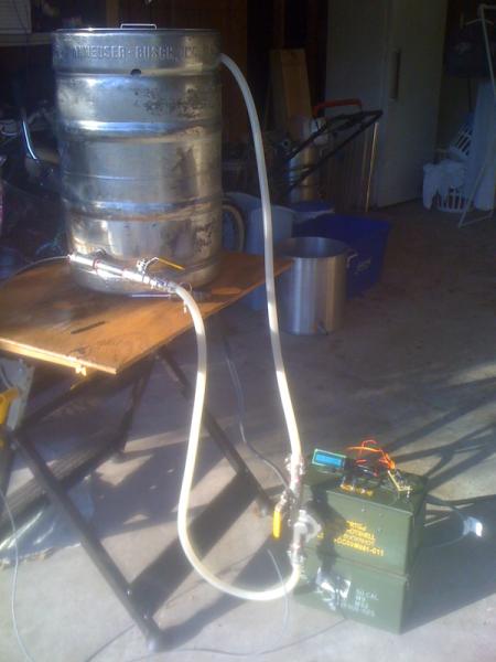
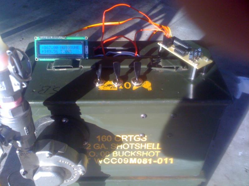
Here it is now. You can see that the Arduino is gone. The 'big' chip there was pulled from it.
There's less than $10 worth of parts there. Once you add the LCD, the value vs a PID drops. However, I have PLENTY of pins left. I already drew another board that adds $0.40 worth of logic chips (thanks Clearwater Brewer!) that will allow me to run three PID loops from this board, and provide power to three vessels, simultaneously, from the same 30A outlet.

image-3906152047.jpg
 
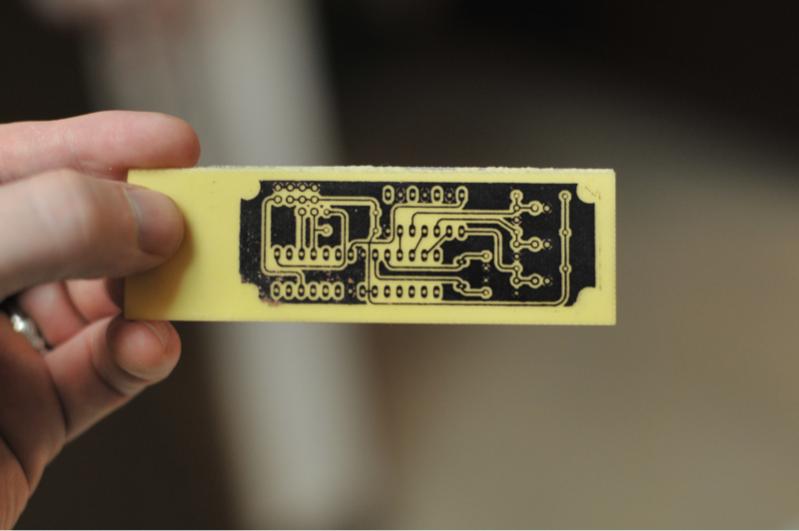
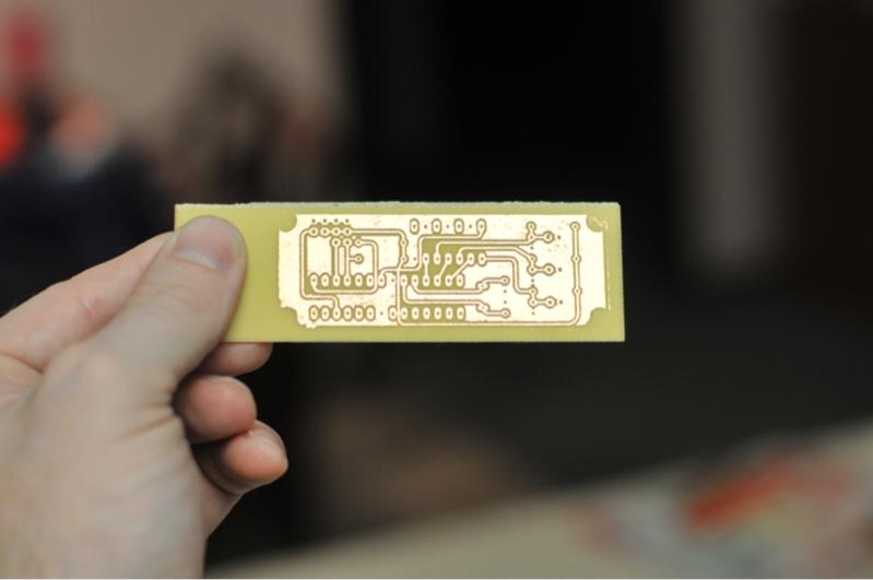
Toner transferred, and the etched board. Thanks to those of you who recommended the Sharpie to clean up the transfer. It works WELL.

For the curious, I switched to Eagle light to draw. I was using ExpressPCB, but have learned that the files are proprietary to their service. Eagle was NOT intuitive to me, but worth learning now that I'm using it. It produces industry standard files that I can send anywhere and have a "real" pcb made for me. Plus, with Eagle, you draw your schematic first. Then when you go to make your board, it links all of your components together correctly, you can name each signal, etc. There is simply no comparison between the two.

image-1031617943.jpg


image-891378452.jpg
 
Great !
I'm doing the same with an Arduino board but for controlling the cooling system (peltier waterblock)...same philosophy...PID + PWM output

very enthusiast of the Arduino DIY automation enabler...and I come from the Arduino orginal Town..Ivrea in Italy where arduino project has been started (Via Arduino is few hundred meter from my house ...)

Davide
 
Why would you add external logic chips to gate PID outputs when you can implement all of that functionality with a few lines of code? You can also make it a lot more intelligent that way. There is one major drawback by implementing it with external chips and that is synchronizing the start of lower priority PID outputs to the next higher priority duty cycle. By implementing this logic in FW you can overcome that limitation.
 
Why would you add external logic chips to gate PID outputs when you can implement all of that functionality with a few lines of code?

Uhm.... because I haven't thought it through that far yet? That would make a lot more sense, though.


synchronizing the start of lower priority PID outputs to the next higher priority duty cycle. By implementing this logic in FW you can overcome that limitation.

This part doesn't make sense to me. In my example, if the MLT and the HLT need to be "On" for the same time, my MLT would "steal" the signal from the HLT, the HLT temp would drop, and the HLT would demand a wider pulse and eventually correct itself.

Are you saying, for example, if I'm using 1000ms windows, and my MLT computes that it needs to be on for 350ms, and my HLT needs to be on for 200ms, I should write it that the HLT pulse begins only when the MLT's 350 ends?

That sounds like the more elegant solution, but confusing to write (for right now). Do you have a sketch that I could look at?

Actually, I'm starting to think it through as I'm typing it.
-The output from the highest priority PID would define the pulse width of the first pin AS WELL AS the interval to wait before writing the second pin high.
-Add the output from PID one and two together, that would define the interval to wait before PID three gets to write high.
-If/when the total output of the three makes it to 1000ms, then the computing period starts over again, regardless of which pin is high at the time.

Is that what you meant?
 
Exactly. You nailed it. I haven't implemented this so I don't have any code to show you how to do it but it will depend on what system you are using and how the PWMs are implemented.
 
One way to implement this would be to manually implement all 3 outputs with a timer ISR. Set up the timer at 100Hz for a 1 second PWM period. If you wanted a 3 second PWM period then go with 33Hz. Have a function that gets triggered from the ISR. In this function do the following:

count++; // increment our counter. There are 100 counts per period.

// check to see if we are at the end of the PWM cycle
if (count >= 100)
{
// we are at the end so reset everything
count = 0;
output1 = 0;
output2 = 0;
output3 = 0;

// enable the highest priority output that is on
if (duty_cycle1 > 0)
{
output1 = 1;
}
elseif (duty_cycle2 > 0)
{
output2 = 1;
}
elseif (duty_cycle3 > 0)
{
output3 = 1;
}
}
else // we are not at the end of the period
{
//check to see if we are at the end of the first duty cycle
if (count == duty_cycle1)
{
output1 = 0;
// check to see which output to turn on next
if (duty_cycle2 > 0)
{
output2 = 1;
}
elseif (duty_cycle3 > 0)
{
output3 = 1;
}
}

//check to see if we are at the end of the second duty cycle
if (count == (duty_cycle1 + duty_cycle2))
{
output2 = 0;
if (duty_cycle3 > 0)
{
output3 = 1;
}
}

//check to see if we are at the end of the third duty cycle
if (count == (duty_cycle1 + duty_cycle2 + duty_cycle3))
{
output3 = 0;
}
}

There are probably some bugs that need to be ironed out here as I am just coding this on the fly. This assumes that the duty_cycle variables represent a throttle percentage of 0 to 100.

You will probably run into a number of corner cases if you try to change any of the duty cycles in the middle of the period. You could get around this a couple of ways. 1 - pull out the code in the first if statement and create a separate function for it. Call this function inside the if statement as well as any time you change the duty cycle. 2 - have 2 sets of duty cycle variables. One set that is changed by external PID algorithms and one that is only changed by this function. At the end of each period when you reset the outputs assign the values of the external duty cycles to the internal duty cycles.

Either solutions would be easy to implement. The first one might not work very well if you change the duty cycles often.

I am not a SW or FW engineer so there is probably a more elegant way to implement this.

[edit] #$&* editor won't preserve my indentations. Copy and paste to a c editor like notepad++ and you can add the indentations back in to make it readable
 
#$&* editor won't preserve my indentations. Copy and paste to a c editor like notepad++ and you can add the indentations back in to make it readable

FYI- You can wrap the code in the [ code ] bracket (# icon in the editor) and it works better
 
Hi

There are a *lot* of places that will do simple PC boards cheap. Some will do overnight processing, others do longer lead for a bit less money.

Bob
 
This project was going pretty well, until this weekend. I'm having a bear of a time with the autotune library for Arduino.

At this point, I'm receptive to any tips you guys have.
 
Sorry to dredge up an old thread, but I am currently fighting with the arduino autotune library and wondered if you made any headway on suitable values for the aTuneStep and aTuneStartValue parameters?

I have built myself a HERMS controller using a custom designed arduino clone and another custom interface board. You may view the build log here. There is also a link to my source code (prior to my attempt to add the auto tune function), and a youtube video of operation.

I'd love some pointers on getting in the ballpark for the aforementioned variables. I'm closing in myself by trial and error, but if someone else has done the hard work already, I'd sure love to benefit from it.
 
I have not been out in the garage in forever. I think those pics from June were the last day I was out there. Sorry I'm not more help.

I'm hoping to get back out there again soon and, if I have any success with the autotuner, I'll post it here.
 
Well, I've been experimenting with it all day, and I finally have it returning some results. The results aren't particularly useful (5.2°C overshoot on a 10°C ramp, compared to a 0.3°C overshoot from my manual tuning), but getting any results at all is still progress!

I'm testing the unit in an electric jug, so not the easiest rig to tune, but all I have until the actual HEX is finished.
 
Well, I am making another attempt at it today. I will let everyone know if I come up with anything useful.

I am really starting to lose my faith in the usefulness of PID for this project. I am starting to think I might just be better off writing my own control script from scratch.

image-1992494086.jpg
 
Well, this time it gave me:

kp: 102.89 ki: 0.06 kd: 0.00

I can't even begin to guess what kind of overshoot that's going to bring on.
I think 102.89 is the local Spanish radio station.
 
hehehe

I think the autotune library is pretty rubbish. It gave me similarly ridiculous results on my test system. I don't question the suitability of PID control, but I think even a moderately well tuned system tuned manually will easily outperform the garbage results from the autotune lib. I suspect that the window size and sample interval may also need to be tuned for a temperature control system like we're dealing with here. I suspect that as the mass of the water being heated increases, an increase of the sample interval will be beneficial.
 
Yeah, I'm NOT QUITE ready to give on PID without overshoot. I've got an Auber PID & RTD that I can use with this very system that does precisely that. I just don't seem to have the skills yet to duplicate it with Arduino.

I am ready, however, to give up on the autotune library. Today was my last shot at it. Tomorrow (I hope), I'm going to start this thing up, let it run at 5% until is stabilizes where ever that may be, and collect some numbers to attempt to manually tune using the Lamba tuning method I've seen elsewhere on the 'net.
 
Instead of sleeping, or doing the dishes or whatever I *should* be doing, I went back out to the garage. I wrote a crude, quick few lines of code. Here's the result:

I had the kettle at 132, then turned on Processing to run the PID front end so I could capture this 20 degree ramp up for you guys:
7990629471_c476e26f45_c.jpg

And here it is a few minutes later, hovering 0.3 degrees under.
7990629885_075ae41801_c.jpg


So, that's a 20 degree ramp in about 4 minutes, with less than half a degree overshoot.

The code is too unpolished to share yet. No PID library, just a pretty primitive set of ifs.

If I'm over the Setpoint, Output is 0
If I'm more than 10 degrees under, I'm at 100%
If it's between, then the Output is just: (50+(Setpoint-Input)/10)

What is that, control guys? Just a "P" controller?

I gave it an extra 50 milliseconds so that when the input dropped back below the setpoint, the controller would go ahead and start back up at 5% instead of something smaller, because I know that's kinda-sorta-close to where I need to be to maintain a temp. I watched for a few more minutes after that second screen, and I never came back up to my setpoint. I'm going to have to change that offset, but not by much, or I'll increase my overshoot. I'm going to increase it to 6% tomorrow and see how it goes.

Still, less than a degree of overshoot & less than a degree of undershoot is nothing to sneeze at. I'm encouraged!
 
Sometimes simple solutions are better suited to simple problems... I am sure the PID library must be well suited to complicated processes, but it looks like in this case your if's are a far better solution.

How did you interface the Arduino with the Processing? Did you program the PID frontend?

Thanks.

Edit: Funny this, I've been tens of times reading the PID library reference, and I've just now realized there is a front-end included!
http://www.arduino.cc/playground/Code/PIDLibrary
http://arduino-pid-library.googlecode.com/files/PID_FrontEnd_v03.zip
Sorry about the basic question.
 
7992057931_7a1792bc14_c.jpg


I'm at it again this morning. That's a 15 minute window. I'm still overshooting 0.5, and then hovering under 0.2-0.3. I'm going to try to work that out, and keep you posted.
 
The code is too unpolished to share yet. No PID library, just a pretty primitive set of ifs.

If I'm over the Setpoint, Output is 0
If I'm more than 10 degrees under, I'm at 100%
If it's between, then the Output is just: (50+(Setpoint-Input)/10)

What is that, control guys? Just a "P" controller?
Your response looks great. You have a good starting point with the conditional logic for the output value. Even with PID control it is not uncommon to use a software manual mode as a type of feed-forward control to preemptively set your output to 100% as you are doing here.

I gave it an extra 50 milliseconds so that when the input dropped back below the setpoint, the controller would go ahead and start back up at 5% instead of something smaller, because I know that's kinda-sorta-close to where I need to be to maintain a temp. I watched for a few more minutes after that second screen, and I never came back up to my setpoint. I'm going to have to change that offset, but not by much, or I'll increase my overshoot. I'm going to increase it to 6% tomorrow and see how it goes.

Still, less than a degree of overshoot & less than a degree of undershoot is nothing to sneeze at. I'm encouraged!

You can eliminate that small amount of error at steady-state with a little integral gain using a PID controller. The problem with only using proportional is never getting to setpoint at steady-state. There are lots of factors that will govern where the controller will settle out: the volume you are heating, the temperature setpoint, the ambient air temperature, a breeze, etc. You might frequently find yourself adjusting that 5% or 6% output "offset".

I think this a great example to show how to set PID gains for water/liquid heating applications like this where you are accumulating heat. A good amount of proportional, a little integral (just enough to eliminate the steady-state error), and optional derivative (if you want to reduce overshoot).
 
Out of curiosity, what type of sensor are you using? Is the accuracy of the sensor really better than 0.2 deg? If not, I'd suggest that you call it good enough and move on to brewing beer instead of tuning PIDs. However, if you're like me then that's probably not an option since you'll know in the back of your mind that it could be controlled a little tighter.

What you've essentially set up is a PID algorithm where you're only using the P control. You have your "P" gain set high enough that the controller output saturates when the temp is more than 10deg from the setpoint. If you want to get rid of the overshoot, you could reduce your gain. You could also use a quadratic or cubic function instead of the linear gain that you currently have. As FastTalker posted above, the I and D gains can help you take care of the steady-state error and overshoot respectively as well.

All of that said, I use On-Off control and really happy with it. I get about 0.5 deg overshoot and virtually zero steady-state error. Even better, there's no tuning and it will always represent the fastest ramp time to get up to temperature. In controls-speak a resistive heater in a well-stirred liquid is about as close as you'll ever get to an ideal integrator, so it's a pretty perfect candidate for On-Off.
 
hehehe

I think the autotune library is pretty rubbish. It gave me similarly ridiculous results on my test system. I don't question the suitability of PID control, but I think even a moderately well tuned system tuned manually will easily outperform the garbage results from the autotune lib. I suspect that the window size and sample interval may also need to be tuned for a temperature control system like we're dealing with here. I suspect that as the mass of the water being heated increases, an increase of the sample interval will be beneficial.


You know, I guess we're also not taking into account WHICH formula the autotune library is written for, either. I'm guessing that this uses the ZN formula, which, by design, *does* overshoot.


Your response looks great.

Thanks!

You can eliminate that small amount of error at steady-state with a little integral gain using a PID controller. The problem with only using proportional is never getting to setpoint at steady-state. There are lots of factors that will govern where the controller will settle out: the volume you are heating, the temperature setpoint, the ambient air temperature, a breeze, etc. You might frequently find yourself adjusting that 5% or 6% output "offset".

Which is exactly what I'm going to try next. I intend the define a "course" band of temperature below the setpoint that uses my control and creates my curve, above. And then a "fine" band around the Setpoint, maybe plus or minus 1.5 or 2 degrees in which the PID library is in charge.

My big gripe has always been the overshoot. The kP, kI & kD may very well be correct for my system; I'll bet they are on a long enough timeline. I'm hoping that if I turn control over to the PID when the slope of the line is closer to horizontal, that it will give me the result I'm looking for.

Out of curiosity, what type of sensor are you using? Is the accuracy of the sensor really better than 0.2 deg? If not, I'd suggest that you call it good enough and move on to brewing beer instead of tuning PIDs.

I'm using a DS18B20. It jumps in 0.11 degree increments. If anyone knows how to get more granularity, let me know! This doesn't keep my from brewing at all, by the way. I can unscrew that thermowell and have my RTD and Auber PID hooked up in minutes. This whole project is just to indulge my inner geek.

However, if you're like me then that's probably not an option since you'll know in the back of your mind that it could be controlled a little tighter.

Precisely that. I'm fully conscious that there's NO WAY my palette is ever going to detect the difference between beer mashed at 151.0 and another 151.5. This is just one of those things I've decided to chase.
 
If not, I'd suggest that you call it good enough and move on to brewing beer instead of tuning PIDs.

Oh, and the other reason I had against just leaving it was that, not only was it off by 0.3, but it was making no effort to correct that error. As fasttalker was saying, I'm guessing that error may be higher in February than in August. Or on a breezy day. Or, worse, that error may accrue instead of being constant, since it reached a "balancing point", so to speak.
 
I'm using a DS18B20. It jumps in 0.11 degree increments. If anyone knows how to get more granularity, let me know! This doesn't keep my from brewing at all, by the way. I can unscrew that thermowell and have my RTD and Auber PID hooked up in minutes. This whole project is just to indulge my inner geek.

The DS18B20 sensors are accurate to +/- .5° C (.9° F) and have a resolution of .0625° C in 12 bit mode. I'm not sure if the accuracy is a function if time/temp/etc, or if it's just a manufacturing result (i.e. does it drift while mashing or not). The resolution won't let you get beyond 0.1125° F however which is what you're observing. The sensors I have seem to be pretty consistent however when I've played with them in the past.

http://datasheets.maximintegrated.com/en/ds/DS18B20.pdf


FWIW, my Auber PID decided that P=124, I=0, D=0 when it auto-tuned itself in my HLT... and it seems to be accurate.
 
Okay..... now I quit.

Here's the last 5 minutes of a small temp change, zoomed way in. You can easily see every 0.11 temp step.

8000103868_81209e3d6f_c.jpg


And the following 5 minutes:

8000104710_21072aeec0_b.jpg


And, finally, a large temp ramp from full throttle. You can see where my sketch hands over control from my line of code to the PID library.

8000104878_6eaf624f59_c.jpg


I'm done, DONE, DONE! (with this part)
 

Latest posts

Back
Top