skifast1 said:
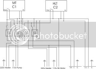
In this case it's actually the intended behavior - the pump switch would circulate the wort but not kick on the heater (for vorlauf). That said, your statement about neither working properly in series means my temp controller won't do the intended job of turning both on. I need to wire them in parallel and still get the pump override switch to work.
In that case, use a SPDT (single pole, double throw) switch, run the common to the pump, tie one side to the hot wire of the heater, and the other side to hot, then you have choice of on, or automatic control
skifast1 said:
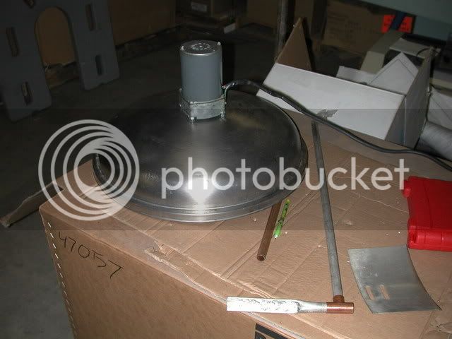
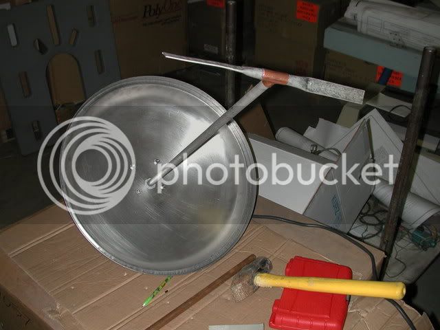
It is in fact supposed to be a HERMS system - what's missing from the schematic is the fact that the heating element is inside a water-filled 3-gallon cooler. The wort is circulated through a 50' copper coil inside the cooler, so no direct contact with the heating element.
where's your temp probe going to be? With how you've described it, I'd be concerned about being able accuratly and quickly maintain temp control. As is, you have two vessels that you'll be using to maintain temp control of one. If you place the probe in the mash, it will cycle when the mash gets low, but since the heating cooler could be at any number of temps (due to different cooling rates, etc) you will probably get greater temp swings than you should with such a system, since you have no direct way of keeping the herms coil from getting too hot or too cold. If you place the probe anywhere else, with the pump off, it won't be indicative of the mash temp.
What I would suggest, to keep with a single controller, is to run the pump continuously, and place the temp probe at the outlet of the herms coil. This will provide several advantages, one, the temp control will be much more stable, as the heater will cycle to keep the herms coil at the right temp, and since you're running constantly, the mash should maintain a consistent temp. It'll also give you a very clear wort (one of the goals of many rims/herms builders), disadvantage, is it will be a bit sluggish in raising the temp of the wort, since you'll also have to heat the extra water in the tank.
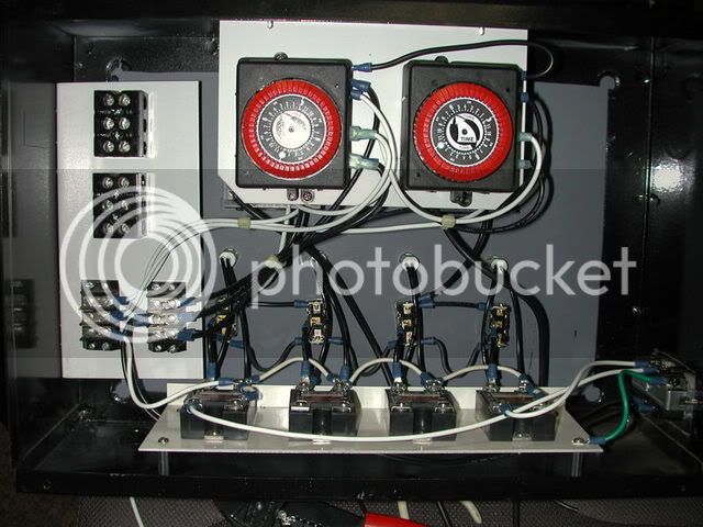
If you don't want to run the pump continuously, you should probably look at a second controller, one to control the heater to maintain the temp for the herms coil tank, and a second to cycle the pump for the mash. This will let you maintain both at a proper temp without wild swings in either, and will allow a quicker response for raising the temp.
One other suggestion, you might consider an agitator in the herms tank to boost the heat transfer efficiency, but this could be a later addition if you'd like.


")


