Marquez
Well-Known Member
67cougargt,
This is a great idea.
Please share when the post goes up.
This is a great idea.
Please share when the post goes up.

PJ, would you mind doing a "test" and trying to upload a file or 2 to my web-server, can send you details to PM if you're interestedP-J is here every day.
My problem now is my version of Windows. The computer I have only supports up to Windows XP and I need to upgrade to a much later PC version to move to a more current version of windows. XP is no longer supported by anyone. I cannot afford the cost of replacing my computer. SO SORRY....
Bottom line -- Getting very old just plainly sucks.
My personal web site no longer supports Windows XP. I can no longer upload diagrams to post on this very important (FOR ME) forum. Basically - The root of my problem in posting info and diagrams.
So sorry to every one. Maya Culpa..
P-J
(Edit) Getting old sucks. I'll be 75 next month. Still pitching & hope I last a liitle more time. Lots of stuff for me to do..
P-J
(/edit)


Trent (and PJ):P-J, I just wanted to say thanks again for all your advice and detailed documentation you've provided. I wanted to speak with you prior to the BYO people reaching out to you but as I understand it they have already talked with you. I hope that it was no problem that your work will be published in an upcoming article, I was sure to give many thanks to you and I just wanted you to know it couldn't have been done without you. Hopefully you know what I'm talking about with regards to the article.
") At first I didn't think a wiring diagram was going to be included so I only recommended they drop the one or two lines in the write-up that explain how the e-stop works. But once the diagram was also sent to me some changes had to also be done to it (as PJ already knows as they contacted him for the edits).
At first I didn't think a wiring diagram was going to be included so I only recommended they drop the one or two lines in the write-up that explain how the e-stop works. But once the diagram was also sent to me some changes had to also be done to it (as PJ already knows as they contacted him for the edits).Trent:
I might as well chime in here and come clean too - The editor of BYO ran your article and PJ's electrical diagram by me too asking for my opinion as I've worked with them in the past on various things.
Generally speaking I thought the article was well written and well thought out (good work). I told them that there are a few things I would have done differently, but that everyone has different needs. From a factual standpoint I didn't find anything "incorrect" about the technical things, which is of course good.
The only thing was I was leery with them including is how the e-stop is wired (shorting power to ground). I recommended that they leave that out as I feel it's an unsafe practice. She ran my thoughts past another electrical engineer who builds UL listed industrial control panels and he agreed with me so the diagram was changed. So you can blame me for that change.
Congrats on the write-up! It's slated for the Jan/Feb issue.
Kal
Just a very curious question for all to ponder:Trent (and PJ):
...
The only thing was I was leery with them including is how the e-stop is wired (shorting power to ground). I recommended that they leave that out as I feel it's an unsafe practice.
...
Just a very curious question for all to ponder:
How does a GFCI circuit breaker test button work?
The E-Stop only allows:
"EPO - wired to trip GFCI main circuit breaker
with small leakage current. ( 0.06A)"
Anyway, you all do as you wish. No problem here.
P-J
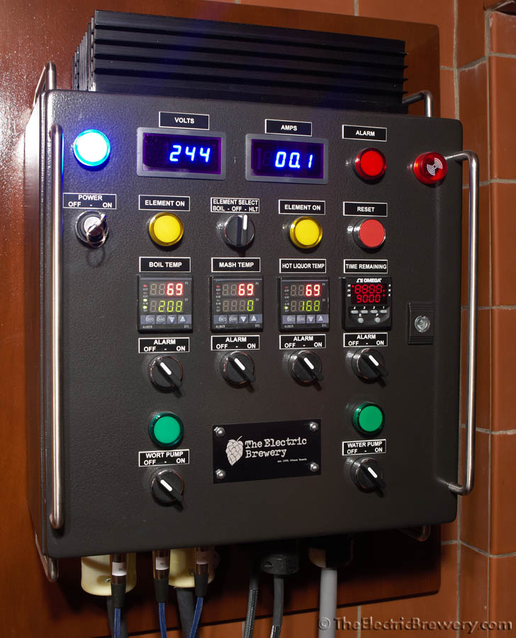
Single Element BIAB 30A PID

So you can do it any number of ways. You can run each wire independently from the terminal strips, or you can pull off anywhere else in the panel. For example, the X2 and 24 portion on the siwtch - just run a short jumper wire from X2 to 24, and then a second wire from either X2 or 24 to the outlet. The wiring diagram is conceptual in nature - the wiring can be run however you need, so long as the connections are made as shown on the drawing. As in, you can do the X2 and 24 switch wiring however, so long as you're not pulling a wire from all the way back at the panel (keep all downstream wiring downstream, all upstream wiring upstream, etc).
Hope that clears a few things up.
-Kevin


(edit) If the pump fuse blows the element could still be fired... Thoughts/solutions?
Question. How does the coil rating of a contactor work? I see PJs diagrams often call for a 240v 30A contactor with 120v coil. What if the coil was rated at 240v?


I tried to route the element just through the contactor, and just the pump through the fuse in such a way that if the fuse blows the contactor breaks the element connection. Did I mess this up?You have your element running through the 4A fast blow - not good.
Sorry. my drawings are based on PJ's diagrams, I figured this was the best place to ask questions. Anyone who needs a schem for a 120v single element single pump RIMS system doesn't quite have an ideal example at the start of this thread, I figured this would contribute to the discussion. (Arduino can be directly swapped for off the shelf PID)Suggest you start your own thread instead of hijacking this thread for your personal project.
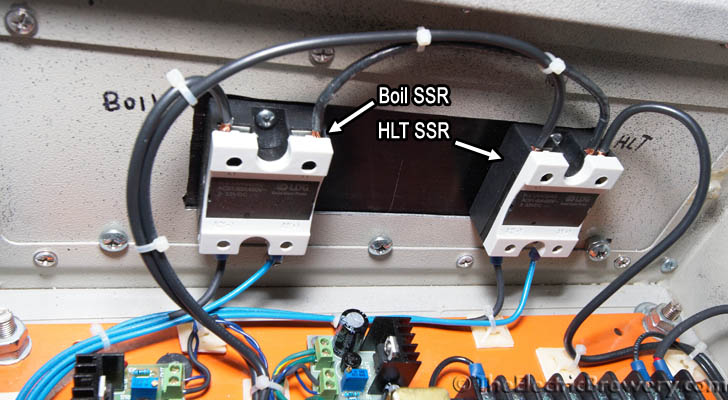
yes, they areQuick question. I'm planning a build based off the diagram below. This may have been already answered, but are these just standard 40A SSRs shown in this diagram? I noticed they look slightly different than the SSRs in the other diagrams.
The SSRs are the same. I used that SSR layout as they are narrow & fit on the page. The other illustrations I use are much wider and would occupy too much space in that particular diagram.Quick question. I'm planning a build based off the diagram below. This may have been already answered, but are these just standard 40A SSRs shown in this diagram? I noticed they look slightly different than the SSRs in the other diagrams.
The SSRs are the same. I used that SSR layout as they are narrow & fit on the page. The other illustrations I use are much wider and would occupy too much space in that particular diagram.
Hope that makes sense.
P-J
You're right - I looked at it wrong. The coil is fed off the 4a fuse, but the element itself isn't. You're spot on.I tried to route the element just through the contactor, and just the pump through the fuse in such a way that if the fuse blows the contactor breaks the element connection. Did I mess this up?
Sorry. my drawings are based on PJ's diagrams, I figured this was the best place to ask questions. Anyone who needs a schem for a 120v single element single pump RIMS system doesn't quite have an ideal example at the start of this thread, I figured this would contribute to the discussion. (Arduino can be directly swapped for off the shelf PID)
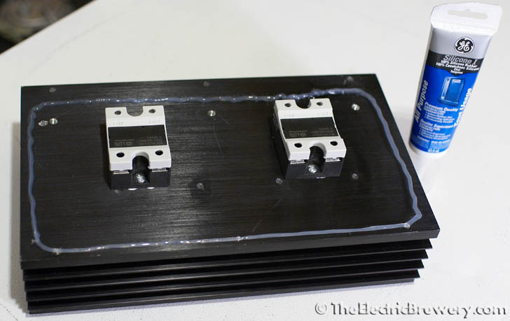
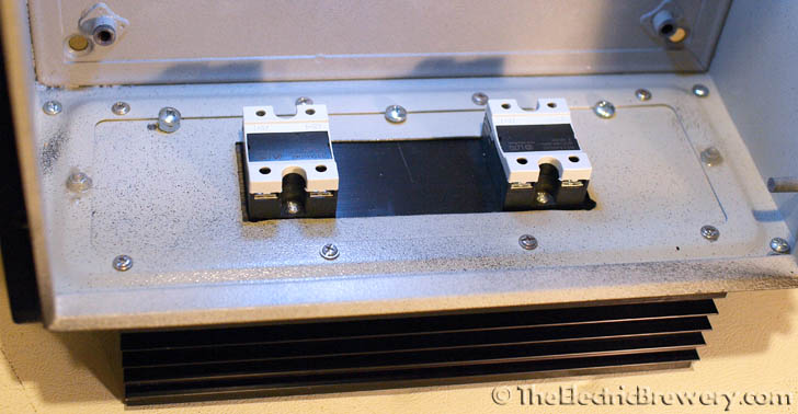
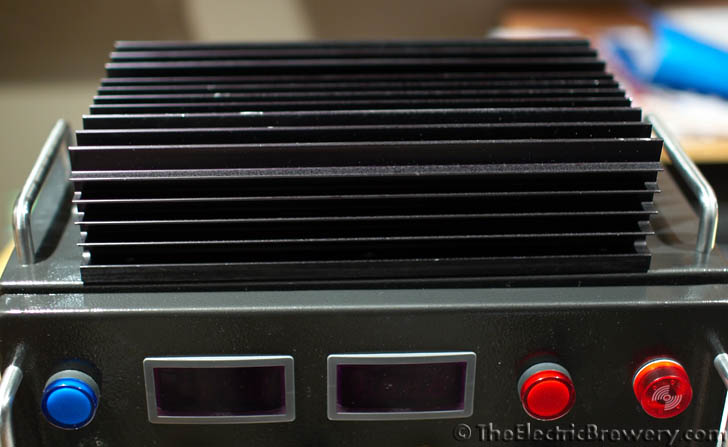
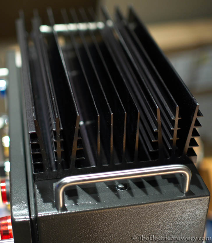
A heat sink is required on any and all SSRs.
Some people put them inside their (sealed) control panels. I prefer to have them outside so that they can release the heat and not cook everything in the panel, shortening the lifespan of not only the SSR, but all of the other electronic devices that use parts that are prone to failure due to heat (most notably electrolytic capacitors).
Kal
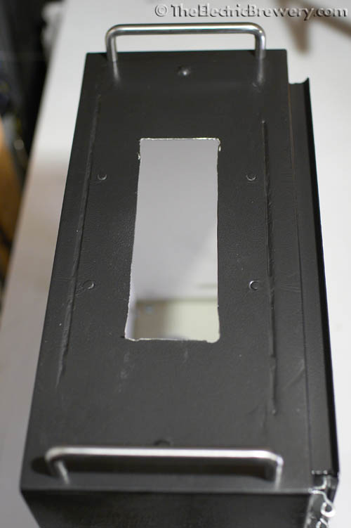
Correct on all accounts.Thanks, can I mount it to the back or top of the box then cut a hole big enough for the ssr to stick though and connect it that way? I'm assuming a bigger heat sink is better?
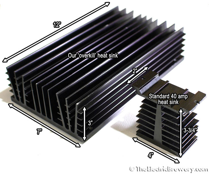
For a single SSR, yes. I would still recommend putting the heat sink outside and using a heat sink meant for a larger SSR than you need. There are no "rules" as to heat sink size so many of the bargain sellers are supplying undersized heat sinks with their SSRs and expecting you to use a fan.Cool thanks for the info... I plan on doing a super simple build (one 5500, pid, no pumps, no extras) so that might be way way overkill?
Enter your email address to join: