Electric brewery build

Homebrew Talk - Beer, Wine, Mead, & Cider Brewing Discussion Forum

Help Support Homebrew Talk - Beer, Wine, Mead, & Cider Brewing Discussion Forum:

This site may earn a commission from merchant affiliate links, including eBay, Amazon, and others.
looks great! Great job on the wiring!

I got my enclosure in today...this is inspiring

...what are the two knobs between the PIDs?
Thanks! We'll be expecting pictures ;)

The knobs are fuse holders for the 1A fuses that protect the PID circuits.

-Joe
 
You....my friend are MAD!!!! awesome !! wish I understood half of what you described in this build so far,I will be better with the....."Welded 2 pcs of 2" angle to hold the......" haha.Will be following...And try to get a cushion on that back destryoyer stool of yours might help the back a little.
 
Wired in the spa panel and 50A, 4-prong outlet. Of course, the plug that I thought was 4-prong is 3-prong and I have to go out for the correct one before I can play.

I did power everything up and meter voltages, as well as test the GFI. All is well in those departments.

spapanel.jpg


-Joe
 
Question for ya:

Are you cutting your existing RTD wires to split for use inside and outside the box, or are you buying additional wire to use between the PID and the internal panel mount RTD connectors?

I was thinking about what to do with mine, and there's pretty much no way to avoid having to recalibrate the RTD with this setup.

TB

I may be wrong but I thought that as long as you used the same type and length of wire, there is no need to recalibrate with the 3 wire RTDs. Anyone know any different?

I'm probably using additional wire. I've got a bunch of 18gu that I've been using for the low amperage bits of the circuits. I figured I'd want to calibrate the RTDs anyway, so it doesn't really matter. I believe the PIDs have provisions for calibration built in.

-Joe

I know the Watlow PIDs I have can be re-calibrated but I don't thinks it's as simple as setting an offset. The manual shows a script where you apply a set voltage/resistance with a decade resistance box to calibrate. This seems a little beyond the tools I have. Has anyone out there actually calibrated a PID this way?
 
I may be wrong but I thought that as long as you used the same type and length of wire, there is no need to recalibrate with the 3 wire RTDs. Anyone know any different?
My bold.

That's the problem. Both Joe and I are extending the RTD wires and splicing in some panel mount connectors, which changes the resistance of the wires going to the PID. Wouldn't that throw off an RTD by a tad?


I know the Watlow PIDs I have can be re-calibrated but I don't thinks it's as simple as setting an offset. The manual shows a script where you apply a set voltage/resistance with a decade resistance box to calibrate. This seems a little beyond the tools I have. Has anyone out there actually calibrated a PID this way?
I'm interested in this as well.

TB
 
My bold.

That's the problem. Both Joe and I are extending the RTD wires and splicing in some panel mount connectors, which changes the resistance of the wires going to the PID. Wouldn't that throw off an RTD by a tad?


I'm interested in this as well.

TB

I may be wrong but I believe that as long as you use the same wire for the splice for all 3 wires, it doesn't matter if it's different from that outside the box. You can't use 16 gauge copper for one, 22 aluminum for another and a coat hanger for the last one though. For thermocouples, it does matter as it is the wire itself (or the junction of the 2) where the temp is being measured (the two different metals define the TC). For RTDs, all you need it to have the same resistance for all three wires.

Any EE nerds out there care to correct me or elaborate?
 
The beauty of RTD Probes is that they can be extended witout worry of a calibration issue. When I made my system, I ordered 6' leads for my PT100 RTD Probes. I was worried the same as you and after much research and asking of electricians at various chemical facilities, RTDs use 3 or 4 wires to measure resistance. The K or S type probes use only 2 and have to be very carefully spliced. I will admit that I don't understand the physics behind it, but my probes were extended 6 feet and they read within 1/2 a degree from my dials and digitals.

Be sure you have the correct setup in your PIDs, a lot of them won't work with RTD's.
 
Finally found a 50A appliance cord at my local Home Depot. I was going to use the Romex-style stuff for initial testing but it's so damn stiff. The appliance cord was a lot easier and neater to wire, too, which makes me happy.

newcord.jpg


newpowerinside.jpg


powerinput.jpg


Broke out the continuity tester for some final double-checking. Good thing I did - I had the PIDs wired to the wrong SSRs. Then it was time to plug it in. The butterflies start...

pluggedin.jpg


Flip the big switch on the control panel and...hmmmmmmmmmm the cooling fan is running! And moving a *ton* of air.

panel_firstlight.jpg


Wooooooooooooooooooooooooooo! Interestingly, the RTDs are 4 degrees off from one another. I'll have to figure out how to fix that. I should have switched them to see if it's the RTD or the wiring inside.

I checked all of the switches and all 4 of the 120v outlets. Everything is wired correctly and works as intended.

So yeah. Exciting! Celebratory Scotch time! Laphroaig, here I come.

-Joe
 
I checked all of the switches and all 4 of the 120v outlets. Everything is wired correctly and works as intended.

So yeah. Exciting! Celebratory Scotch time! Laphroaig, here I come.

-Joe

Congratulation, well done:mug:

Cheers,
ClaudiusB
 
Next we wire up the heatstick and hlt and do some boiling tests so I can get used to the PIDs. Then I'll work on getting the RTDs calibrated properly.

-Joe
 
Very well done! And great pick on the celebratory Scotch.

I may have missed it in a previous post but do you have an open air port to help with the exit air from the fan?
 
Thanks all! I didn't take a picture of it, but I drilled a bunch of holes in the back panel to allow exit air.

-Joe
 
The offset is easy to set on those PIDS. Just take a look in the manual for the temperature reading offset. Just adjust it so the reading is correct and you are good to go. Mine was off by something like 11ºF.
 
How are you securing your elements to your kettles?

I'm just about done with my wiring; just two more wires to go (the grounded shielding on the RTD wires inside the enclosure) then I'm starting on my kettles as well.

TB
 
Finally found a 50A appliance cord at my local Home Depot. I was going to use the Romex-style stuff for initial testing but it's so damn stiff. The appliance cord was a lot easier and neater to wire, too, which makes me happy.

Broke out the continuity tester for some final double-checking. Good thing I did - I had the PIDs wired to the wrong SSRs. Then it was time to plug it in. The butterflies start...

Flip the big switch on the control panel and...hmmmmmmmmmm the cooling fan is running! And moving a *ton* of air.


Wooooooooooooooooooooooooooo! Interestingly, the RTDs are 4 degrees off from one another. I'll have to figure out how to fix that. I should have switched them to see if it's the RTD or the wiring inside.

I checked all of the switches and all 4 of the 120v outlets. Everything is wired correctly and works as intended.

So yeah. Exciting! Celebratory Scotch time! Laphroaig, here I come.

-Joe

Congrats!!!

Good lookin build you got going.
 
Good news - it works! And I learned something about the PID. Pictures first. You may remember my 
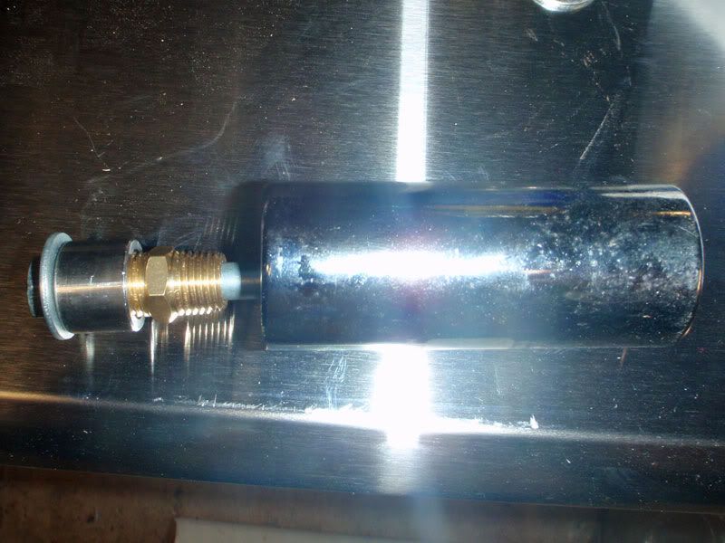
Heatstick of Doom construction thread. I finished that up tonight.

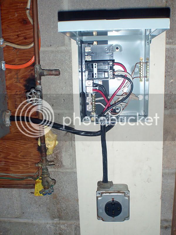
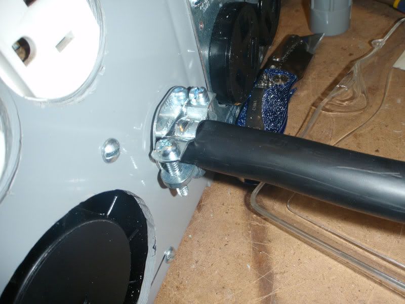
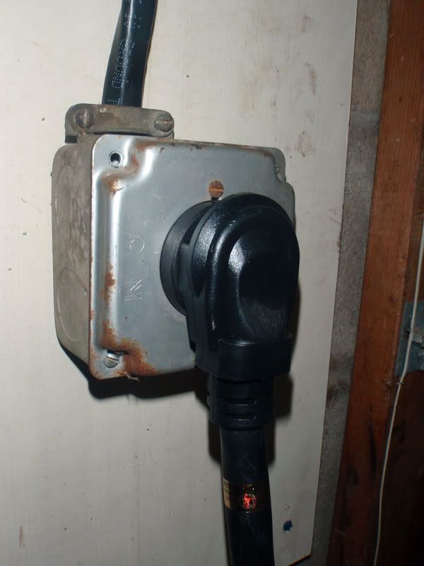
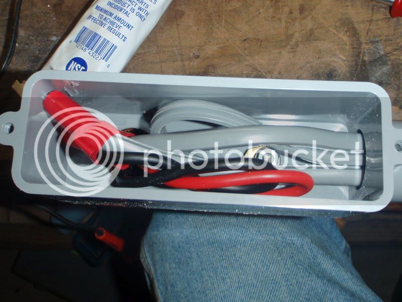
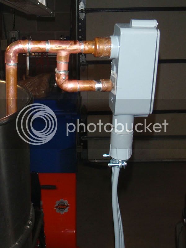
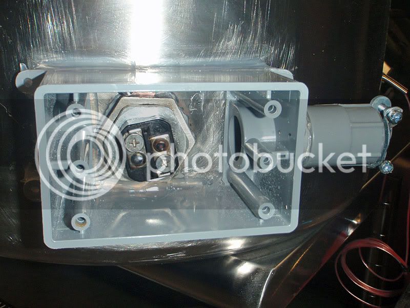
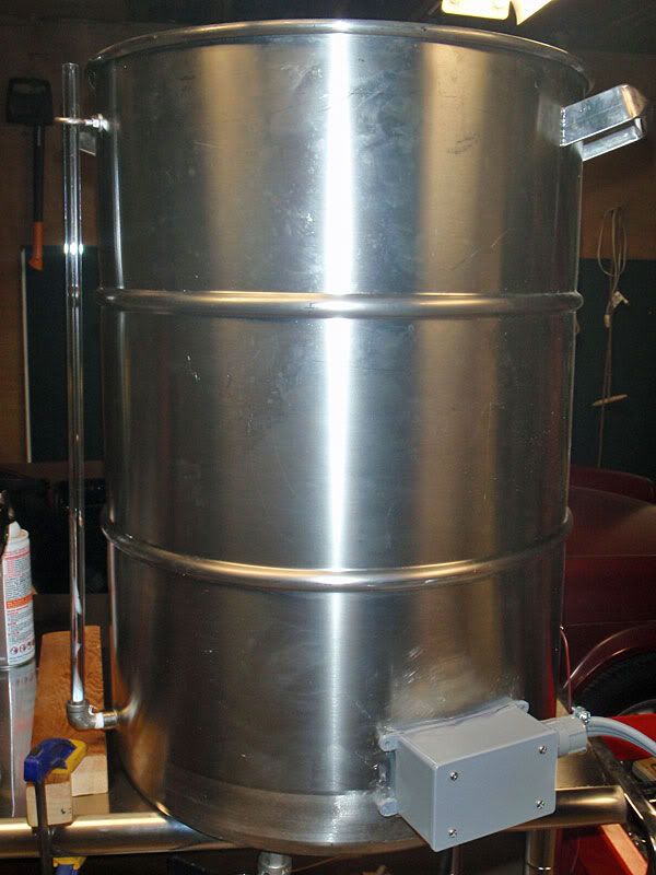
Attached an outdoor junction box to the top and wired it up.

heatstickwiring.jpg


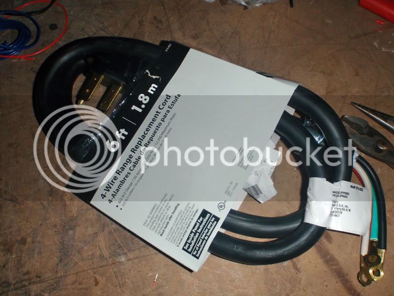
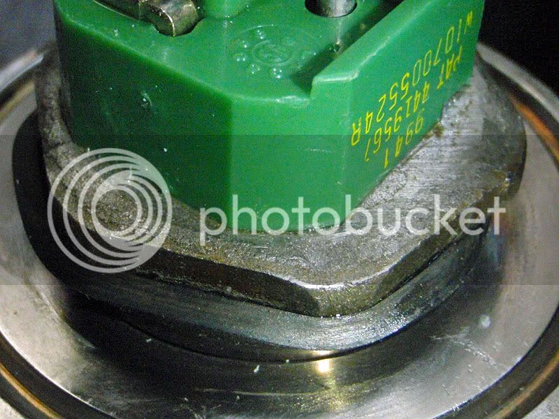
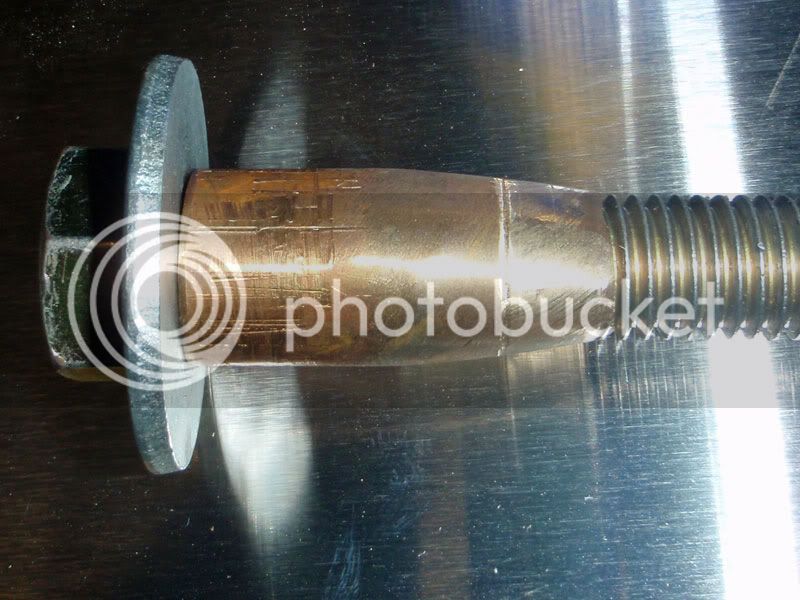
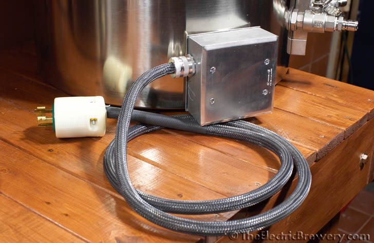
Then I wired in the element.

heatstickelementwired.jpg


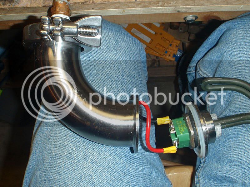
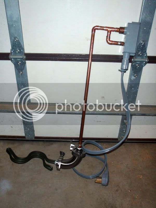
And the completed heatstick.

heatstickcomplete.jpg


Here's a closeup of the top of it hanging out of the kettle. That copper framework there both supports the box and provides a grounding lug so the whole thing has a safety ground back to the main.

heatstickinkettle.jpg


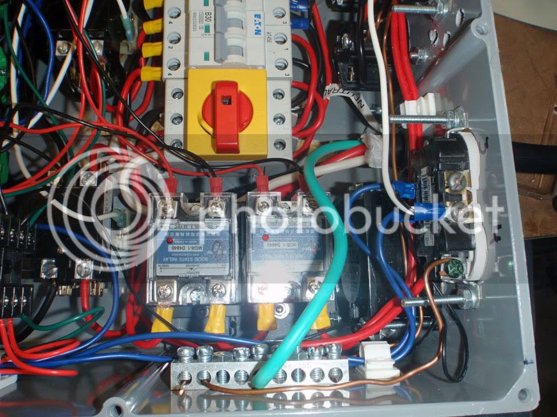
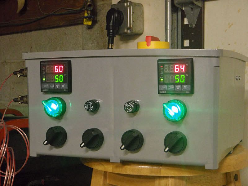
Now what did I learn? Well, the PID has a setting for cycle time, t. From the factory, t = 2. This means a 2-second cycle time, such that if you set the manual mode to 20%, the element will be on for 0.2 seconds and off for 1.8.

Now the manual says for PID use, go with t = 2. Other folks on this forum have said to go with t = 0 to get a 0.5 second cycle time. So I tried it.

With t = 0, if I set the PID in manual mode to anything less than 50%, it was just off constantly. If I set it to 50% or more, it was on constantly. Once I set t = 2, the element cycled appropriately.

Then I was playing with setting t = 1 and back to 2 when my GFCI breaker tripped. I hope it was just an artifact of me messing with the settings while the element was running and not a leak in my heatstick :/ I'll know tomorrow.

Moral of the story: listen to the manual :)

Video is processing now.

-Joe
 
I see the logic in putting the probe in the recirc plumbing but do you think it would be useful to monitor heating progress on the PID display also? If so, I guess it's only 100% accurate if you recirculate during heating. Do you feel its indirect location is close enough for that purpose?

OT: It would be really nice if a system like this could tell you that the probe has been reading 212 for the last 14 minutes or whatever in case you got distracted and want to know where you stand in your planned timeline.
 
It's close enough that I can use the readout to know when I'm close to boiling. I was going to put it in the side of the kettle, but I figured I'd start this way as I can always drill holes later.

I had also considered adding a piezo buzzer, as the PIDs allow you to set an alarm value. So I could set it at say, 190 and go do other setup/cleaning and wait for the buzzer to go off. Or it could let me know when my HLT is up to temp.

I want to insulate the tuns first. Although 40 minutes is pretty good. According to my calculations, 100% efficiency would be around 30 minutes.

-Joe
 
Bad news/good news. Bad news: the heatstick was full of water. Good news: the GFCI works :)

I had previously leak-tested the heatstick, and it was fine. Not sure how it happened, but it looks like the gasket oozed out of place at some point. Guess I'll have to look for something a little stiffer.

badgasket.jpg


-Joe
 
...

OT: It would be really nice if a system like this could tell you that the probe has been reading 212 for the last 14 minutes or whatever in case you got distracted and want to know where you stand in your planned timeline.

Part of the reason I ended up going with a BCS... data logging.
It collects the data and you can see a graph anytime:

RIMS_Heater1.JPG
[/QUOTE]
 
Yes, there will be a 90 degree elbow and a hose barb on the inside to shoot the wort around the side of the pot.

-Joe
 
I think we're still talking about that same port. If the wort is flowing from your chiller into that port with the probe on it, you're measuring the output of the chiller, not the temp of the wort in the kettle. You need a probe either in the vessel, or on the output port of the kettle to the chiller, to know when to stop chilling. Is that port with the probe the output to the chiller or the kettle input for whirlpooling after the the chiller? Because you keep calling it a whirlpool port. This wouldn’t be the first time I’ve been completely confused and not been able to see what’s going on. Help me understand this :drunk:
 
Hmmm.... I was mistaken. I would recommend measuring temps wherever the liquid is leaving the vessel, not where it is returning to the vessel. I had a momentary brain fade.

It may work where you have it, but it seems less accurate than possible.
 
Man nevermind, you said back on post 71 that you were using an immersion chiller. We already talked about this...

Carry on, nothing to see here.
 
It may work where you have it, but it seems less accurate than possible.
I'll have to try it out and see. For this application I don't care if it's off 2-3 degrees. As long as it's near where I want to pitch, I'm happy.

Now in the HLT, the RTD is directly in the side of the vessel and there will be a stirrer motor for more accurate measurements.

-Joe
 
Rather than mail order, went to my local big box and found a harder rubber replacement gasket. It's sitting in the water testing now. If it's dry after an overnight test, I'll do another hot test.

In the meantime, finished up the HLT. First, here's the dimple tool for a 1/4" NPT coupler. It's a 1/2" brass long nipple ground to a taper on my belt grinder. The same 5/8" bolt fits through it perfectly.

small_dimple_tool.jpg


I use a pair of calipers and check frequently so I know when to stop pulling it through. When it's close but not quite there, I switch to this setup to pull the actual coupler through.

5/16" bolt goes through the coupler, which is threaded into a random 1/4" nipple I had lying around. That keeps it centered. I use a 1" deep socket on the outside, since it's almost a perfect fit around the dimple.

pullthrough_tool.jpg


Once it's pulled through, we end up with this.

sightglass_pulledthru.jpg


Apply solder as before and...

sightglass_solder.jpg


Last thing to do is wire up the element. I used a 3/4" outdoor box with the bottom cut out. I used clear adhesive silicone to stick it in place. Seems very solid, but I'm going to keep an eye on it to see if I need to do something more drastic.

hlt_power.jpg


And the final product, complete with a sightglass kit from Bobby_M.

hlt_finished.jpg


-Joe
 
Back
Top