My new RIMS control panel

Homebrew Talk - Beer, Wine, Mead, & Cider Brewing Discussion Forum

Help Support Homebrew Talk - Beer, Wine, Mead, & Cider Brewing Discussion Forum:

This site may earn a commission from merchant affiliate links, including eBay, Amazon, and others.

EvilBrewer

Well-Known Member
Joined
Nov 19, 2008
Messages
193
Reaction score
9
Location
Maryland
Thanks a lot to everyone who helped me out and answered my questions as I fumbled my way through building this thing. The control panel itself is not extremely unique; I drew most of my inspiration from the posts of others who had done something similar. That's the main reason I'm posting my results ... seeing what others had done was a HUGE help to me.

I haven't brewed with it yet, but everything works as intended. Need to hook it all up and do some more tests...very excited for the first brew day!

First off, this is the wiring diagram that I used as a reference; I actually grabbed this diagram from another post; it was created by P-J...to whom I say thank you very much...this was extremely useful. My actual wiring is slightly different in that I have 2 pumps, and I also didn't switch my neutral lines. But the hot lines are switched as indicated in the diagram...and I wired the PID's output to the SSR as in the diagram such that the element won't get any power unless Pump 1 is on:
wiringdiagram-56901.jpg


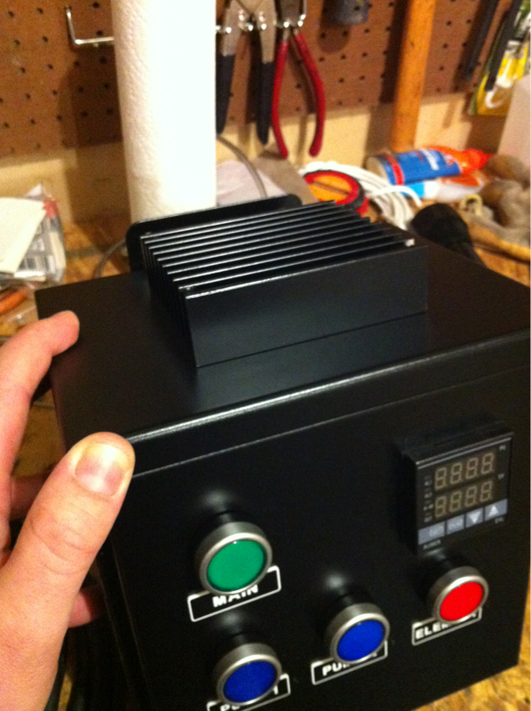
Here's the final shot...HUGE thanks to The Electric Brewery for the design inspiration:
image-1034226450-74be16979710d4c4e7c6647856088456.png


Heat sink mounted on the top (again, hats off to The Electric Brewery for the idea!):
image-3781119810-74be16979710d4c4e7c6647856088456.png


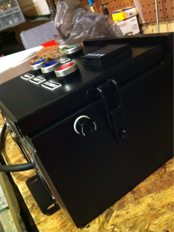
Outlets for pump 1, pump 2, and the heating element; input for temperature probe:
image-1016214900-74be16979710d4c4e7c6647856088456.png


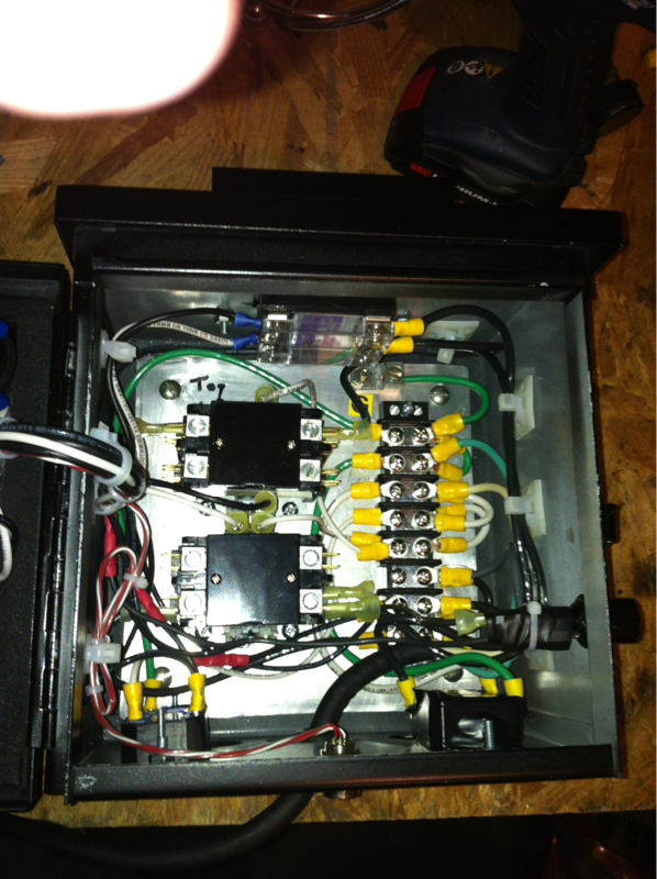
1 amp fuse on the power supply to the PID (the PID is an Auberins SYL-2352):
image-2607666239-74be16979710d4c4e7c6647856088456.png


Shot of all the wiring. Just slightly more organized than a rats nest, but I'm pretty happy with it...I figure it's not too bad for a first timer:
image-3776645136-74be16979710d4c4e7c6647856088456.png


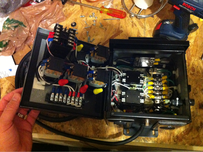
Closer shot of the wiring inside the box:
image-3525169316-74be16979710d4c4e7c6647856088456.png


Closer shot of the wiring on the inside of the door:
image-8967147-74be16979710d4c4e7c6647856088456.png


Cheers.
 
I love seeing a more simplified design. I see that you have 2 pumps but one element. I am guessing that is because....actually I dont get it. If you have one element, why do you need 2 pumps?
 
NewBrewB said:
I love seeing a more simplified design. I see that you have 2 pumps but one element. I am guessing that is because....actually I dont get it. If you have one element, why do you need 2 pumps?

I use an immersion chiller with recirculating arm for cooling wort. I use a march pump to move the wort through the recirc arm and a submersible pump in a bucket of ice water to move "coolant" (ie, ice water) through the chiller. I only switch over to ice water (from using regular tap water) once the wort is about 90-100ish degrees. Anyway, pump 2 is the submersible pump :)
 
gForcex64 said:
Where did you purchase the enclosure?

I bought it on eBay. Basically just did a search for the size I wanted until I found something reasonably priced. This enclosure was like 20-30 bucks. My advice is to get something slightly bigger than you think you'll need; this one ended up being pretty cramped after I installed everything...it all fits of course, but it would have been easier if I'd had more space.
 
Since it's a phrase that I can't say often enough, nice box! I am finishing up a much simpler (for now) RIMS system myself. I hope to have as many buttons as you some day.
 
Jon73 said:
Since it's a phrase that I can't say often enough, nice box! I am finishing up a much simpler (for now) RIMS system myself. I hope to have as many buttons as you some day.

Haha...thanks!
 
gForcex64 said:
Did you use the contactor? Do you need the contactor?

Pete G

Yes and yes. A contactor is a type of relay so you don't necessarily have to use a contactor per se but you'll want to use some kind of relay. There are actually two contactors in the box; one for the main power, and one for the power to the element. The second is downstream of the first. Here's a link to a discussion that I found useful when I was researching the topic:

https://www.homebrewtalk.com/f170/how-build-control-panel-part-1-a-199643/index30.html
 
One more question. Which switches did you use? 1NO/1NC or the 2 NO. SW1 or SW11, if you know the part #s?

The switches have 2 N.O. contacts (SW1), but the only one that really needs to able to switch two components is the one for the main pump (The switch for "Pump 1" in my control panel). It switches power to the pump while simultaneously switching the PID's low voltage output to the SSR...effectively so that you cannot power your element unless your pump is on. You might already konw this, but the reason for wiring it like that is so you don't risk powering your element without liquid flowing through your RIMS tube. I think even having liquid idle in the tube can be trouble if the element is on...boiling/scorching I guess. But without any liquid it can ruin the element...my understanding is that it will burn itself out fairly quickly.

Anyway...I got just about all my parts from Auberins. Here you go:

Switches

SSR

Heat Sink

Temperature probe (with optional "deluxe" cable)
 
garrettbuckeye said:
looks fantastic! where did you get the labels for your control panel?

Thanks a lot! I got them here: http://www.binameplate.com/

I had never ordered electrical labels before so I don't know how their prices compare to others. But I really liked their site; walks you through a wizard for customizing your labels and shows you a preview, etc.
 
The switches have 2 N.O. contacts (SW1), but the only one that really needs to able to switch two components is the one for the main pump (The switch for "Pump 1" in my control panel). It switches power to the pump while simultaneously switching the PID's low voltage output to the SSR...effectively so that you cannot power your element unless your pump is on.

for the pump: Is this equivalent to a DPST toggle switch? In the "off" position, no power is delivered anywhere. When in the "on" position, it completes both circuits?

For the other ones: do you have one contact that has nothing wired to it?
 
for the pump: Is this equivalent to a DPST toggle switch? In the "off" position, no power is delivered anywhere. When in the "on" position, it completes both circuits?

For the other ones: do you have one contact that has nothing wired to it?

You are correct. The switches are all the same; most are only using one of their two contacts. There's also a third connection for each switch--which may not be completely clear from the diagram--that supplies power to the LED inside each button to illuminate it when it's in the "on" position.
 
You are correct. The switches are all the same; most are only using one of their two contacts. There's also a third connection for each switch--which may not be completely clear from the diagram--that supplies power to the LED inside each button to illuminate it when it's in the "on" position.

Cool, I wasn't exactly sure!

Just a few last questions. Why do you have a contactor after your main power switch? I brought this up with Kal, and he (I think) agreed that if everything is on a 120V circuit, you can use a switch that can handle the 15-20A without the use of a contactor.

With your second contactor- the one immediately before the element- why do you feel it is necessary? Is it just another safety precaution? The way I see it, is that it will switch as soon as the SSR switches. If that's true, why would you use a type of relay that isn't supposed to be switch on as much as an SSR? (I've heard that contactors are only supposed to swtich a couple times over an extended period).

Thanks for the help,
Jay
 
My switches are not rated for the current that is drawn by the the control panel...hence the main contactor. The second contactor is a way for me to cut off power to just the heating element while leaving everything else on. For example, when transferring wort from MLT to kettle during the sparge, or during the boil. I could have just turned off the PID but there are instances where I want to monitor the temp of recirculating wort (with the PID display) when the element is off. Plus, I read that SSRs can often fail and when they do, it is usually in the "on" position. In that situation I want to be able to cut off the element manually...via the contactor.
 
EvilBrewer said:
My switches are not rated for the current that is drawn by the the control panel...hence the main contactor. The second contactor is a way for me to cut off power to just the heating element while leaving everything else on. For example, when transferring wort from MLT to kettle during the sparge, or during the boil. I could have just turned off the PID but there are instances where I want to monitor the temp of recirculating wort (with the PID display) when the element is off. Plus, I read that SSRs can often fail and when they do, it is usually in the "on" position. In that situation I want to be able to cut off the element manually...via the contactor.

That makes a lot more sense. I'm going to be using 20A toggle switches, which means I don't need the first contractor. I'm going to include the second one for safety, as Kal (and you) said, SSR fails in the 'on' position while a contact or fails in the 'off' position.

Thanks for your help EvilBrewer!
 
Thanks for all of the information and pictures in the post. I am going to order my parts this week. One quick area of clarification. I am new to complex electrical diagrams so I will lean on a friend to help put this together.

However I did have a question. From what I can tell I need to order two of the Contracters (To enable the pump to be run independently but otherwise pair the motor with the heating element). It appears from the pictures that only one SSR is needed. I wanted to be sure I only need one SSR. I guess I don't understand why you don't need to pair the SSR with each contracter. From the Electric Brewery pages it appears they pair a SSR with a mechanical relay.

Thanks for sharing all of the information. It's very helpful.
 
AuTrappiste said:
Thanks for all of the information and pictures in the post. I am going to order my parts this week. One quick area of clarification. I am new to complex electrical diagrams so I will lean on a friend to help put this together.

However I did have a question. From what I can tell I need to order two of the Contracters (To enable the pump to be run independently but otherwise pair the motor with the heating element). It appears from the pictures that only one SSR is needed. I wanted to be sure I only need one SSR. I guess I don't understand why you don't need to pair the SSR with each contracter. From the Electric Brewery pages it appears they pair a SSR with a mechanical relay.

Thanks for sharing all of the information. It's very helpful.

If you are using one element, you technically only need a single SSR. However, the contractor downstream of the SSR is used as a secondary safety, as SSRs tend to fail closed (allowing electricity to pass through it. A mechanical relay will prevent this.

You will need another contractor (not another SSR) if your switches are not rated for the current drawn by the element. (Or that's at least how the EvilBrewer explained it to me).
 
Awesome - Thanks for the help JayMac. One other question. When mashing do you just leave the valve from the mash tun to the pump & RIMS tube open so the PID will control things without monitoring. I assume this is what must be done unless one were to get an automated value.
 
Contactor = mechanical relay.

You don't need two contactors. In fact you don't need any contactors. On the other hand, if you're using a switch for the element that isn't rated to 20A then you'd need the switch to control a contactor that is rated to 20A. Supposedly this provides some measure of additional safety as you don't have to physically touch a switch that has full voltage running through it (assuming the switch can handle the current), but this argument is used for 240V systems and higher amperage heating elements. In this case 120V is at both element and switch, regardless of the use of a contactor.

IMO the contactor for main power is unnecessary...it's a safety feature (if you can think of a situation where you'd need it), but probably more for bling and extra buttons. It's a design feature from kal's panel (he argues it's so he can keep kids from using the panel or whatever, but he uses a key operated switch)...a lot of people copy it, even down to the ammeter and voltmeter, but it's not necessarily the best design.

A 20A/120VAC toggle switch is $4 from home depot. If you want to use those fancy switches, then it gets more complicated.

One more criticism of this design: although it's designed so the SSR doesn't receive a signal unless the pump switch is on, a better design would be to couple the hot line for the element contactor with the pump switch instead, as that would also account for a situation where the pump isn't on but the SSR is failed open.
 
AuTrappiste said:
Awesome - Thanks for the help JayMac. One other question. When mashing do you just leave the valve from the mash tun to the pump & RIMS tube open so the PID will control things without monitoring. I assume this is what must be done unless one were to get an automated value.

Although I'm currently in the midst of receiving my parts, I can answer your question from what I've gathered from other posters.

You keep the valve on the outlet of the MT fully open, and slightly open the valve on the OUTLET of the pump. It's the valve on the outlet that will allow you to control your recirculation rate, at the start of recirculation, you want to barely open your outlet valve. If you open it a lot, the bed will compact and give you a stuck sparge.

There is no need for automated valve, as the flow meter would never be able to tell you how much the bed is compacting. Plus if everything is automated, what's the fun?!

Remember, ball valve goes on outlet of pump, not inlet!
 
AuTrappiste said:
Awesome - Thanks for the help JayMac. One other question. When mashing do you just leave the valve from the mash tun to the pump & RIMS tube open so the PID will control things without monitoring. I assume this is what must be done unless one were to get an automated value.

I think your questions have been answered by others but lemme know if anything was overlooked. Also here's my $0.02...

With a RIMS, the wort must always be flowing when the element is on...stopping the flow of wort can cause the "stationary" wort to boil inside the RIMS tube (not good) and unfortunately this can't be automated--ok...within reason. The RIMS won't have power when the pump is off, true...but you could have the pump on (and element activated) and accidentally leave one of the valves closed...hence stopping wort flow and boiling inside the tube. You can run the element dry in almost the same way. I did that on RIMS brew session #2...it sucked but luckily I had bought a backup element :)

And as others have said, use the outlet valve on your MLT to throttle wort flow, rather than the outlet valve on the pump.

SSRs...saw it mentioned already but yes it is there for the sake of the element. It can cut power on/off much faster than a contactor...and it is meant for doing just that.
 
EvilBrewer said:
And as others have said, use the outlet valve on your MLT to throttle wort flow, rather than the outlet valve on the pump.

Actually...scratch that. I was thinking of something else--you shouldn't use valves downstream of the pump to throttle flow bc it can put too much pressure on the tubing. Not valid in this case.
 
SSRs...saw it mentioned already but yes it is there for the sake of the element. It can cut power on/off much faster than a contactor...and it is meant for doing just that.

This statement is not necessarily correct. Inside the SSR there is a triac that turns off only when the voltage next crosses zero, which may be up to 1/120 second for 60 Hz AC. Release times for solenoid relays and contactors vary but are typically in the range of milliseconds.
 
EvilBrewer said:
I think your questions have been answered by others but lemme know if anything was overlooked. Also here's my $0.02...

With a RIMS, the wort must always be flowing when the element is on...stopping the flow of wort can cause the "stationary" wort to boil inside the RIMS tube (not good) and unfortunately this can't be automated--ok...within reason. The RIMS won't have power when the pump is off, true...but you could have the pump on (and element activated) and accidentally leave one of the valves closed...hence stopping wort flow and boiling inside the tube. You can run the element dry in almost the same way. I did that on RIMS brew session #2...it sucked but luckily I had bought a backup element :)

And as others have said, use the outlet valve on your MLT to throttle wort flow, rather than the outlet valve on the pump.

SSRs...saw it mentioned already but yes it is there for the sake of the element. It can cut power on/off much faster than a contactor...and it is meant for doing just that.

I'm still wiring up my system, but I went on eBay and bought a stainless steel GEMS flow switch (FS-10798 Series) for $50. As long as I have 0.5 gallon/minute flow out of the RIMS (this is adjustable to 20 GPM) and through the switch, the switch will turn close, which in turn allows the heating element to turn on. No flow, no juice to the SSR that controls the RIMS. I'm using it to protect a 2000W/120VAC water heater element... And my wort.
 
Namako said:
I'm still wiring up my system, but I went on eBay and bought a stainless steel GEMS flow switch (FS-10798 Series) for $50. As long as I have 0.5 gallon/minute flow out of the RIMS (this is adjustable to 20 GPM) and through the switch, the switch will turn close, which in turn allows the heating element to turn on. No flow, no juice to the SSR that controls the RIMS. I'm using it to protect a 2000W/120VAC water heater element... And my wort.

I stand corrected :)

I've got to say, that's a great idea and I might need to copy it. I've already burned out one element and have come close to doing it again a couple of times.

I literally have "TURN OFF ELEMENT" written in huge bold font on my brew day sheet for the steps that involve transferring wort from MLT to kettle, ha.

...And yes I have a written procedure that I follow on brew day (and update regularly)...helps cut down on attention-deficit-related distractions when I've got 10 things going on at once!
 
EvilBrewer said:
I stand corrected :)

I've got to say, that's a great idea and I might need to copy it. I've already burned out one element and have come close to doing it again a couple of times.

I literally have "TURN OFF ELEMENT" written in huge bold font on my brew day sheet for the steps that involve transferring wort from MLT to kettle, ha.

...And yes I have a written procedure that I follow on brew day (and update regularly)...helps cut down on attention-deficit-related distractions when I've got 10 things going on at once!

You mean during lautering that you burn out your element right? Not during recirc.
 
JayMac said:
You mean during lautering that you burn out your element right? Not during recirc.

Yup. Did I say while recirculating? If so then it was in error. I burned out the element while transferring from MLT to kettle. So yeah while lautering or maybe the initial draining of MLT. I was batch sparging.
 
EvilBrewer said:
Yup. Did I say while recirculating? If so then it was in error. I burned out the element while transferring from MLT to kettle. So yeah while lautering or maybe the initial draining of MLT. I was batch sparging.

You didn't, I was just making sure! I'm building a similar set up and that's why I made the comment. I'll learn from your mistakes :D
 
EvilBrewer said:
I stand corrected :)

I've got to say, that's a great idea and I might need to copy it. I've already burned out one element and have come close to doing it again a couple of times.

I literally have "TURN OFF ELEMENT" written in huge bold font on my brew day sheet for the steps that involve transferring wort from MLT to kettle, ha.

...And yes I have a written procedure that I follow on brew day (and update regularly)...helps cut down on attention-deficit-related distractions when I've got 10 things going on at once!

I've also experienced pump cavitation more than once... Everything looks to working, all the switches are set right, pump is on, but no flow. I figured a flow switch would at least keep me from boiling the wort in the RIMS, eventually burning out the element... And this 2000W puppy doesn't come cheap!! ;)
 
Back
Top