jvino
Well-Known Member
You are a pro!!! I hope you can find time to weld up mine when I get the project together. Looks great!!!

Update: May 10, 2010

Update: April 10, 2010
Amazing build, man. You are really good.
Why does it split on the top like that?
Sorry I know I am a newbee. But I have 1 question Did you have to drill out your burners to work with the low pressure lp gas? I have been reading all the forums and now im lost.
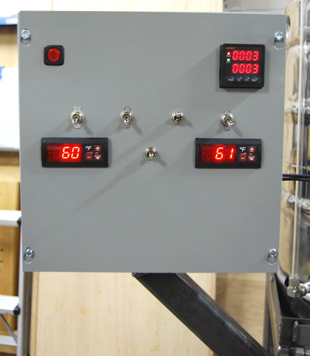
Can you put up a picture of the inside of the panel? How much room is between the end of the controlers and the box?
") . Our wire color matching went to hell because we ran out of wire and weren't going to go get a spool - we know what goes where so we're happy with it.
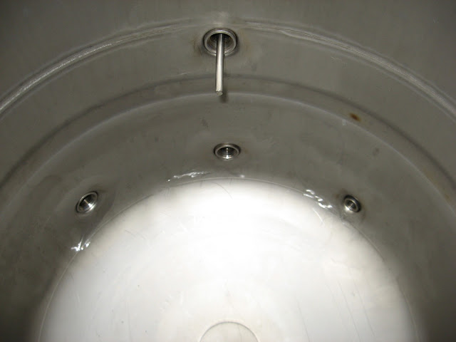
. Our wire color matching went to hell because we ran out of wire and weren't going to go get a spool - we know what goes where so we're happy with it. Do you have any diagrams as to where the fittings are on the kegs and the purpose?? I finally sourced some kegs and plan to get started on my HERMS system soon. It would be helpful to know measurements as it seems to work well for you. Thanks!!
Matt,
I'm loving your system. I've looked at plenty of various HERMS setup and components, but I love your design: not too complex and utilized a good design with smart components. My future setup will be pretty close to yours.
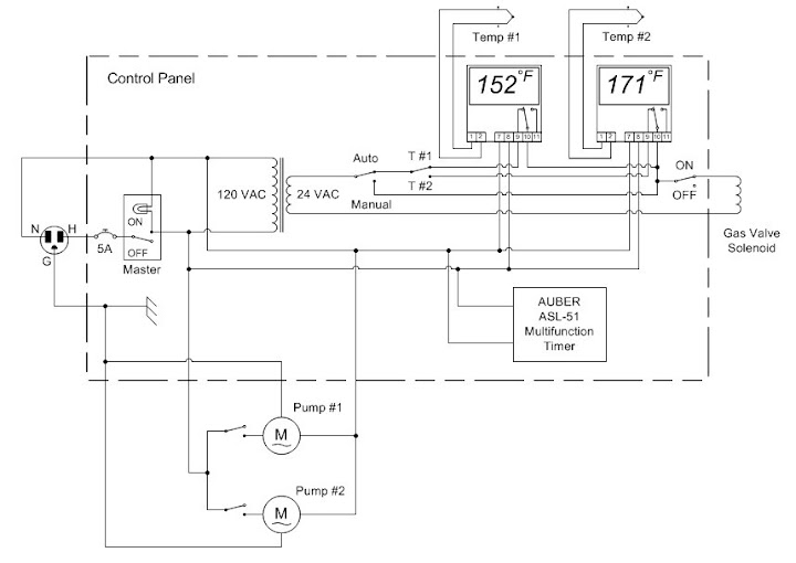
A few questions. How exactly did you wire the timer? I've used the Love controllers on my kegerator but have never used a timer. Your wiring diagram was great but didn't show the timer.
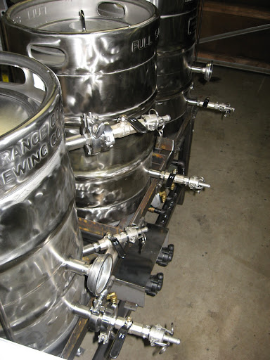
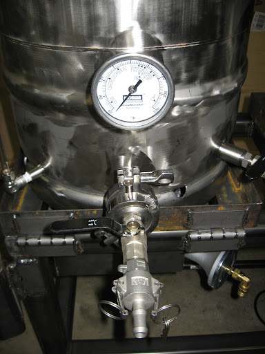
On your cam-lock connections (brilliant by the way), do they have any internal rubber rings? Just curious if everything is good for high temp.
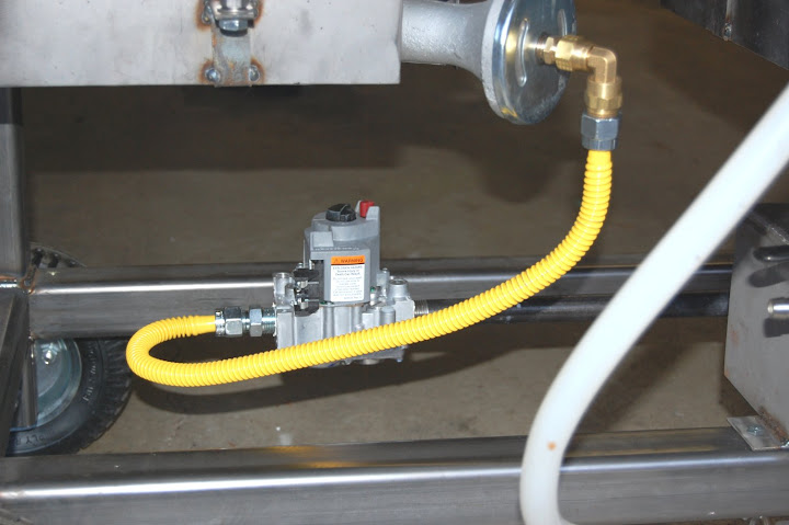
Lastly, I'm going to be using the furnace solenoid valve, thermocoupling, and pilot light direction. Where did you get your 2-stage regulator? Do you have a make and model?
What size inlet and outlet did you get?
I figure your pipe supply for the burner would need to be a little larger than the size to each burner. The two-stage regulator does everything for you correct? You won't need a regulator on the BBQ tank right?
Anywho, It is a lot to digest. I think you guys have developed a brilliant rig. Thanks for the great documentation too.
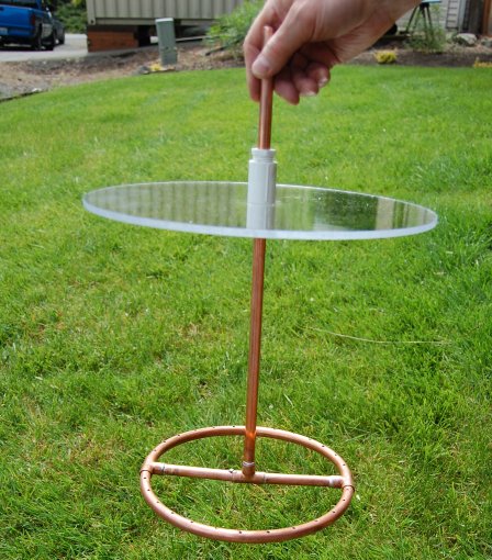
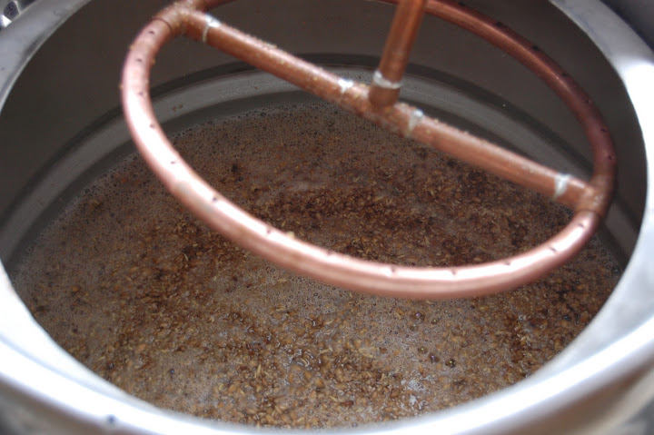
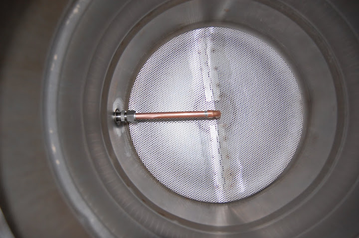
Any problems with your sparge arm staying put? I have a similar set up but have not developed a means to hold it at the height I want. That means I end up sitting there holding the damn thing with a hot pad! Super Fun and inefficient!
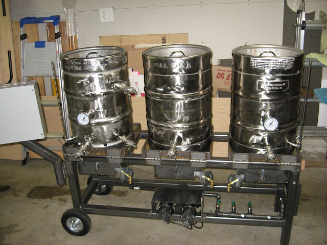
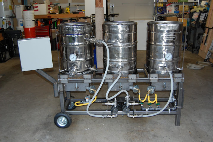
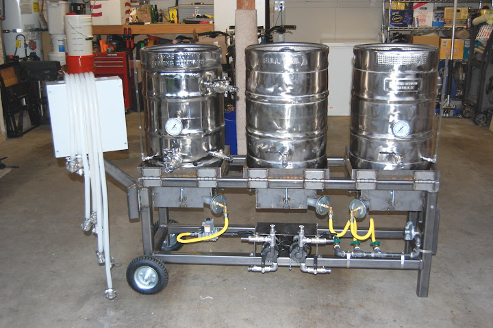
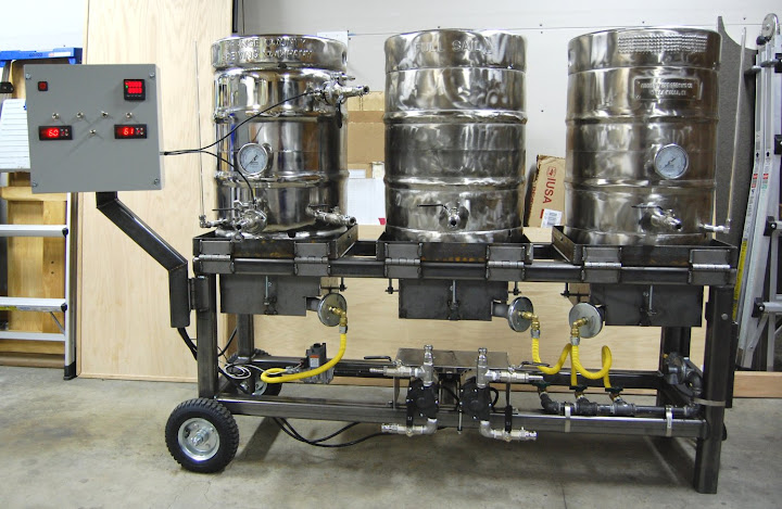
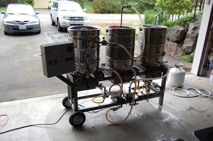
I ran in to that same problem, and rather than raising the kegs up, I cut 2 6"x1" vents in the skirt on each keg. It worked great, and was easy. (Especially if you know someone with a plasma cutter.)Update: June 4, 20102) Our BK and HLT seem to be suffocated when the kettles are resting on the frame. If we prop them up just slightly (a bolt head) they gain enough oxygen to breath and burn appropriately. We're going to play around with options to raise up our kettles and leave a little breathing room between the frame and the tip tray. We'll post updates when we get to that point. The bolt head works for now though - just have to be careful not to go grabbing a piping hot bolt! Guess our wind screens/design to prevent the wind and heat issues was too efficient!

I ran in to that same problem, and rather than raising the kegs up, I cut 2 6"x1" vents in the skirt on each keg. It worked great, and was easy. (Especially if you know someone with a plasma cutter.)
Enter your email address to join:
