Kevin's E-Brewery Build

Homebrew Talk - Beer, Wine, Mead, & Cider Brewing Discussion Forum

Help Support Homebrew Talk - Beer, Wine, Mead, & Cider Brewing Discussion Forum:

This site may earn a commission from merchant affiliate links, including eBay, Amazon, and others.

KevinWagner

Supporting Member
HBT Supporter
Joined
Dec 30, 2011
Messages
37
Reaction score
0
Location
Seattle
Hey All,

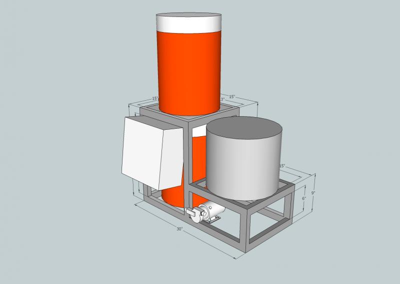
My electric brewery build.

Even before I start, thanks to everyone on this forum, from which I've found the answers to almost all of my questions.

My design philosophy is:
* I like to brew often -- so I'll stick with a 5 gallon capacity.
* I want it to be compact -- so it'll be mobile and store easily.
* Everything attached -- so stuff doesn't go missing between sessions.
* No lifting -- 2-tier with a pump.
* I want to brew indoors -- Electric.

Here is the system as it is in my imagination:

Thanks,
Kevin
brewery_5.jpg
 
Hey All,

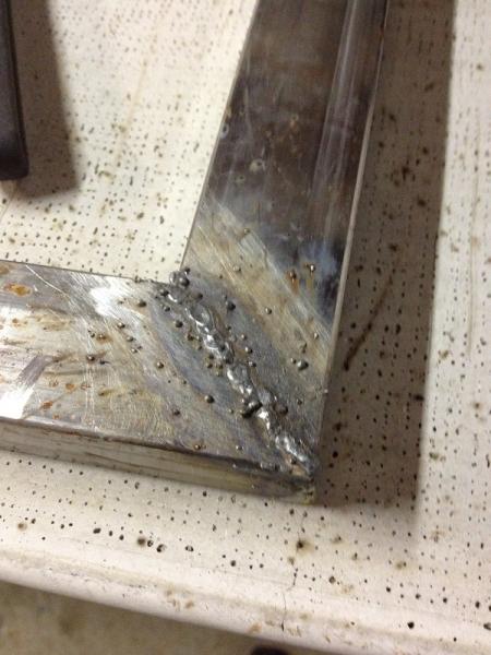
I've cut all the steel tube for the brew-stand.

1x1.5x0.065 steel tube from OnlineMetals, which happens to be local.

Using a HF 90A Flux-Core Welder #98871.

Haven't done any welding since high-school shop some 15+ years.

Ugly welds = lots of grinding!

Thanks,
Kevin

Cutting_Parts_IMG_0584.jpg


Corner_Weld_IMG_0589_small.jpg
 
I would bevel the steel where the 45 degree angles come together. It will give more room for the weld to fill in. That band saw probably makes really clean cuts where the metal fits perfectly. After grinding a weld there probably is not much weld left, hence bevel the joints. Actually those weld are not too bad for a flux core machine.
 
Hey All,

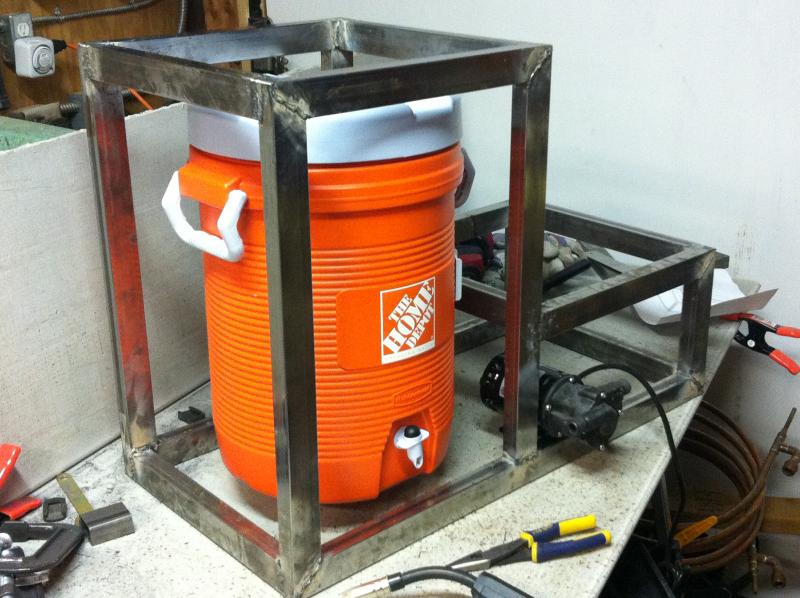
Here is the frame all tacked-up, and test fitting the HLT and pump.

I think the placement of the control panel is going to interfere with connecting the hoses, and in being able to see the thermometer, on the HLT.

I am considering hanging it off to the left side of the brew-stand.

Biggest challenge I've had with welding has been with burning through the thin-walled tube.

Coming together nicely nevertheless!

Thanks,
Kevin

IMG_0609.jpg
 
I would bevel the steel where the 45 degree angles come together. It will give more room for the weld to fill in. That band saw probably makes really clean cuts where the metal fits perfectly. After grinding a weld there probably is not much weld left, hence bevel the joints. Actually those weld are not too bad for a flux core machine.

I still have loads of clean-up to do, and on the corners particularly. I wanted to round the corners, so they wouldn't be sharp -- and would have the same radius as the long edges of the ajacent tube -- and realized I was grinding the corner welds completely off! Thanks for the tip!

Thanks,
Kevin
 
Nice and compact...I'm going to follow this as I may be moving to San Fran this summer and at prices out there I know I will suddenly have a lot less room to brew.

Looks good so far!
 
I still have loads of clean-up to do, and on the corners particularly. I wanted to round the corners, so they wouldn't be sharp -- and would have the same radius as the long edges of the ajacent tube -- and realized I was grinding the corner welds completely off! Thanks for the tip!

Thats the beauty of metal, if you make a mistake just grind it down and reweld it! I always say that wood is easier to cut and work with but metal is more foregiving.
 
Hey All,

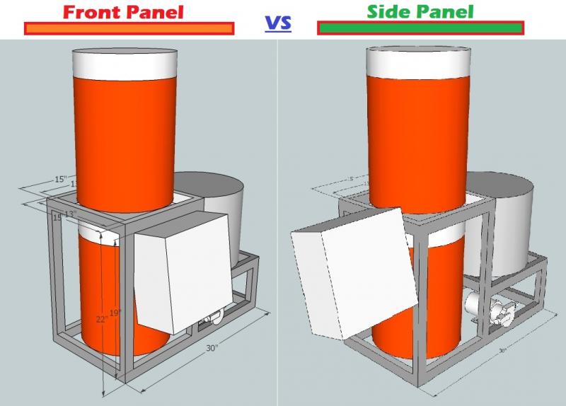
I'm debating the best place for the control panel.

I originally planned to put the 12x12x6 PVC box in front of the HLT. Looks like it would interfere with connecting hoses and reading the thermometer on the HLT.

I like the idea of having it on the front, because that keeps the cart compact, and having it on the left increases the overall length.

Having it on the left, on the other hand, makes the HLT more accessible. It will also allow me to tilt the panel back more, making the face of it more perpendicular to a user's line of sight.

Thanks,
Kevin

brewery_5_control_compare.jpg
 
I would think you might want it a little higher so you don't have to bend over to use it.
 
I agree with the height and on the left would work best, and you can also put it on hinges to keep the length down.
 
I also vote for the left and think that mounting it higher would be best as well. I am side mounting my control box on the side as well on my single level eHERMS build. great start.
 
Hey All,

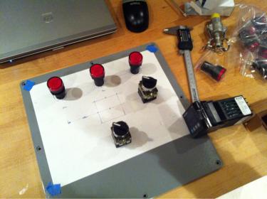
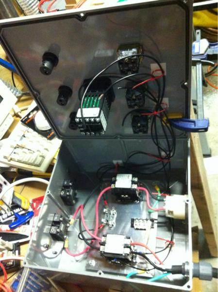
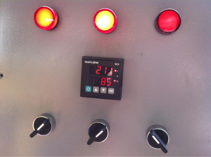
Time for some control panel assembly. This part of the build should look familiar to everyone by now.

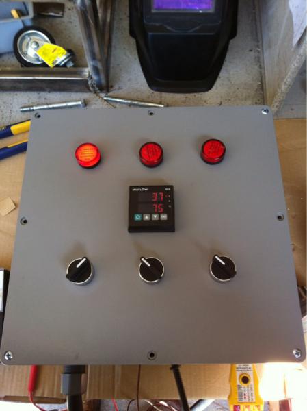
Using a Watlow type 93 controller. Three switches and pilot LEDs, one each for mains power, element on/off, and pump.

Stankonia said:
Are you going to end up putting a heating element in the HLT cooler??

I don't plan a HLT element for the initial build. First go-round is single infusion+sparge, but you know, maybe tomorrow I decide it needs HERMS.

Thanks,
Kevin

image-1546164124.jpg
 
Hey All,

I'm debating the best place for the control panel.

I originally planned to put the 12x12x6 PVC box in front of the HLT. Looks like it would interfere with connecting hoses and reading the thermometer on the HLT.

I like the idea of having it on the front, because that keeps the cart compact, and having it on the left increases the overall length.

Having it on the left, on the other hand, makes the HLT more accessible. It will also allow me to tilt the panel back more, making the face of it more perpendicular to a user's line of sight.

Thanks,
Kevin

What about on the left, up closer to the level of the MLT, sideways? Does that make sense? It would keep the small footprint, but be higher and accessible from the side.
 
I don't plan a HLT element for the initial build. First go-round is single infusion+sparge, but you know, maybe tomorrow I decide it needs HERMS.

Thanks,
Kevin

so, you'll use the BK to heat water for the mash and sparge? And just pump it into the HLT?

I had an Igloo HLT and I had an element in it controlled with a digital Johnson controller, and it worked great, if you ever decide to go that route.
 
I don't plan a HLT element for the initial build. First go-round is single infusion+sparge, but you know, maybe tomorrow I decide it needs HERMS.

Thanks,
Kevin

So before you drain your first runnings you'll heat up the sparge water and pump it to the HLT cooler where it will sit until you are ready for it? Or would you drain your first runnings to the HLT, then add the sparge water from the kettle, then transfer your first runnings from the HLT into the kettle?

I'm liking your design so far, just trying to get an idea of how you plan on using it on a brew day.

Cheers
 
Stankonia said:
So before you drain your first runnings you'll heat up the sparge water and pump it to the HLT cooler where it will sit until you are ready for it? Or would you drain your first runnings to the HLT, then add the sparge water from the kettle, then transfer your first runnings from the HLT into the kettle?

I'm liking your design so far, just trying to get an idea of how you plan on using it on a brew day.

Cheers

The former. I'll heat the sparge water in the kettle then transfer it to the HLT. Then pump the sparge water from HTL to the the Mash while gravity takes the runnings to the kettle.

Essentially what I have been doing, but without all the lifting.

-Kevin
 
Question regarding the single pump setup and how you have three vessels:
How are you utilizing each?

I've been looking as Joshua's design
https://www.homebrewtalk.com/f170/modular-electric-brewery-177852/
and working off that as far as simplicity goes. You have the HLT on the bottom, MLT on top and BK on the side?

I also am trying to use an existing 10g cooler as a MLT. BK/HLT sits on top, drains into the MLT (cooler) lower and to the side. Gravity brings strike and mash-out water to the MLT while a pump pushes back up to the BK. Two vessels.

By all means, not trying to question your design, trying to understand so that I may better mine.

Thanks a bunch,
Todd.
 
Question regarding the single pump setup and how you have three vessels:
How are you utilizing each?

...

By all means, not trying to question your design, trying to understand so that I may better mine.

Thanks a bunch,
Todd.

Todd, Stankonia,

I’ve created a process diagram as I've imagined it (yeah, paintbrush). I've tried to render it with all of the equipment as it is located on the brewery for clarity.

The HLT is just a holding tank for the heated sparge water, and frees up the boil kettle to accept the sweet wort.

This is essentially a two tier system, and I suppose the tanks could be placed in any configuration – mash, HTL, or kettle on top. The common factor is, you can use gravity for one transfer, but need a pump for the other two.

Thanks,
Kevin

Process_Flow_Diagram_Small.jpg
 
Kevin I love your build. I live in a rental house so this is the perfect size for me! I hope you don't mind copying some of your design. My goal is to start building with in the next few weeks.
 
Kevin I love your build. I live in a rental house so this is the perfect size for me! I hope you don't mind copying some of your design. My goal is to start building with in the next few weeks.

Hardly any of it is my own design. Most of it is lifted from the dozens of other documented builds here.

Here are some more control panel assembly pictures.

Thanks!
Kevin

IMG_0619.jpg


IMG_0624.jpg
 
Hey All,

Here's a photo of the current state of the control panel, sitting on my bench. Anytime anyone asks me how long a project like this takes, I say, about 10 hours -- in ten minute increments over 6 months. :)

-Kevin

image-1238113179.jpg
 
Nice build! I really like how compact everything is.

Where did you get the selector switches in the CP?
 
The enclosure is the 12x12x6 PVC box from Home Depot. The pilot lamps and selector switches were both E-Bay purchases. Shipped from Hong Kong and were cheap, but took weeks to arrive.
 
Hey all,

I finished building the control panel and there are a couple of issues.

1) the SSR is always closed, even when the signal lines are disconnected (measured as 120v between the load-side and common, or as 240v between load side and the other phase). Is my SSR blown?

2) the temp reading on the Watlow93 seem to go down when I apply heat to the temp probe.

Thoughts?

Thanks,
Kevin

image-1205838622.jpg
 
If you temperature sensor is a thermocouple, try reversing the leads; also, make sure any configuration parameters in the controller set-up are correct.

SSR's leak a little - try putting a 100w light between the load side & common and see how it responds by looking at its relative brightness.
 
Junkster said:
If you temperature sensor is a thermocouple, try reversing the leads; also, make sure any configuration parameters in the controller set-up are correct.

SSR's leak a little - try putting a 100w light between the load side & common and see how it responds by looking at its relative brightness.

Thanks Junkster, you're two for two.

Swapped the + and - on the thermocouple leads and now it works. Funny since the leads were marked ... incorrectly!

Also, with a 75w lamp wired in, the SSR is switching correctly.

I'm reading about SSR reset failure and yes, it seems most SSR do leak on the load side, and a load must be greater than the leak in order to reset.

So, question is, is the leak enough to get you in trouble in any situation where you expected the circuit to be cold? Good thing I wired a contactor load side or the SSR.

Thanks,
Kevin
 
Well, if the SSR is controlling something that draws a fair amount of current like a heating element, then I wouldn't think there would be a problem. I think I read somewhere that the leakage current is a few milliamps which won't drive much of a load. It would probably light an LED indicator if the main load is removed or went open.

I'm still in the building stage of mine, so I haven't crossed that bridge yet..... I think there are some pretty good threads about it on this board somewhere.
 
I just brewed my first batch on July 4, and while waiting to see if it turned out OK I've been reading this forum.

This build looks fantastic, but when in the heck do you all find time to brew?

Cheers, swill
 
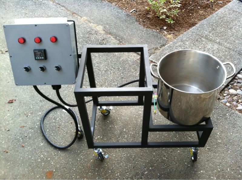
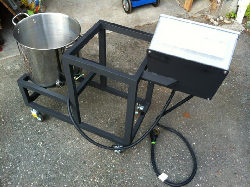
Here's where it's at.

Went over the frame with an 80 grit flap wheel to take off surface rust and polish it up. Painted with BBQ paint.

Installed the casters.

Attached the control panel.

Drilled the kettle and installed the 3000w element.

To Do: Lots of stuff! Build decks for each of the levels, wire the element, install pump, etc, etc.

Sorry it's taking so long!

Edit: It's a 3kw element, not a 4.5kw.

-K

image-265208170.jpg


image-3005483271.jpg


image-3563816320.jpg


image-3156806323.jpg
 
Wet test today!

Let's see... set a mash-in temp of 160 deg F. Beep-boop.

Sweeeeeet.

Update: Took 35 minutes to raise from 66 to 160 deg F.

Update: and another 29 minutes to boil.

image-3304675469.jpg


image-4145333051.jpg


image-937318792.jpg
 
Is that a high watt density element? If so you may want to swap that out for an ultra low watt density to eliminate potential wort scorching.

Also, are you still planning to mount the pump at the same level as the HLT? You may have problems with priming the pump when you are pumping from the HLT to the MLT - it might work OK if you had enough water in the HLT the head pressure may be enough to prime the pump, but normally people mount them below the vessels.

Cool setup though.

Edit: Also, are you using GFCI protection (spa panel, GFCI breaker)?
 
bigljd said:
Is that a high watt density element? If so you may want to swap that out for an ultra low watt density to eliminate potential wort scorching.

Also, are you still planning to mount the pump at the same level as the HLT? You may have problems with priming the pump when you are pumping from the HLT to the MLT - it might work OK if you had enough water in the HLT the head pressure may be enough to prime the pump, but normally people mount them below the vessels.

Cool setup though.

Edit: Also, are you using GFCI protection (spa panel, GFCI breaker)?

It's a low watt density ss element, it's folded back once. Hard to see in the photo.

I did plan to mount the pump at the level of the HLT. I expected that head pressure would prime it.

Edit: I bought one of the 16ft 30amp cords with in-line CFGI from Hosfelt. http://www.hosfelt.com/contents/en-us/d702.html#p5341

Thanks!
 
More of the kit on the cart.

Added pine-wood decks on each level, pretending they are mahogany.

Couldn't wait for it to be finished and brewed on it this week anyway. The kettle works great, 3kw is more than enough power. Actually a lot more control over the boil than with propane.

Still need to install the pump and counter flow chiller. Looking forward to eliminating the manual transfers.

IMG_1010.jpg
 
Back
Top