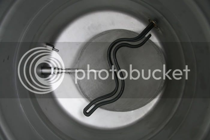
Last question... is this 304 or 316 stainless screen?
It's 304ss.

Last question... is this 304 or 316 stainless screen?
Beautiful work on your keggle! I'm not a welder so I have a lot of respect for those of you that can make such nice welds at home! I had mine done by the "pros" at SABCO and I can say that yours are just as nice!

Dig your progress so far man.
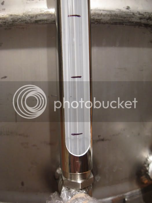
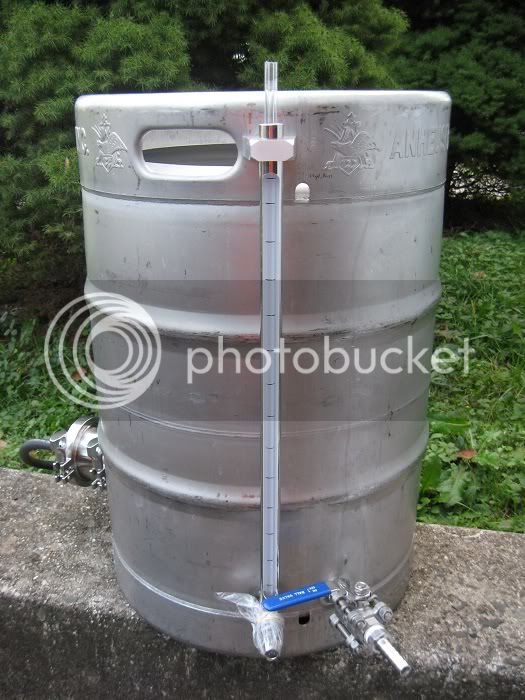
Marking the sight tubes was a *****, X2 (HLT & BK). Make sure you've got an accessible supply of the good stuff when filling & marking!
TB
Oh, we did! It took a while to do just this one keggle, but not too too long. We calculated the weight of a gallon of water in grams and weighed one gallon at a time on a digital scale down to the gram. It should be pretty damn close. After 15 rounds we were done!
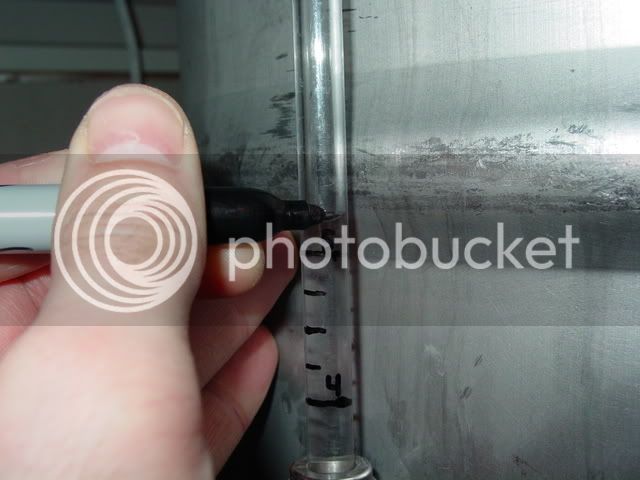
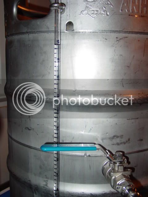
I ended up marking mine in quart increments, so I filled two keggles one quart at a time!
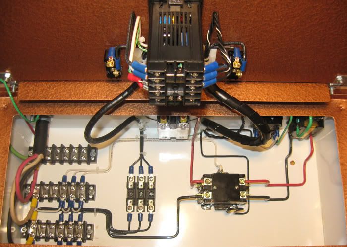
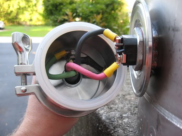
Beautiful wiring job!
Geebus, is that a control panel or a wiring diagram? Very clean work indeed!
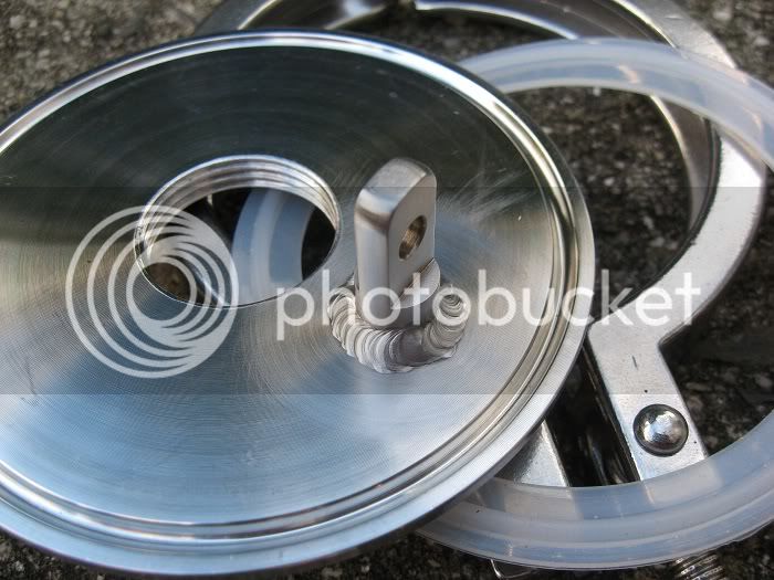
I have a question about the sight glass how did u make the or were did u buy the stainless piece holding the polycarbonate tubing? Love this build I may have to copy some of it great work! Cheers!
What size o-ring did you use for the element?
Jtkratzer,
The o-rings are McMaster #9396k38.
Kevin,
I really like the design with the tri-clamp with a drilled end cap and rubber grommet. When you say you're going to go to a tri-clamp removable element when you need to replace the existing element, are you going to buy it that way or weld it up yourself?
I haven't looked hard for tri-clamp elements, but the one I did find was $180. http://www.brew-magic.com/bm_part_element.html
Thanks for the tip about the lock nut.
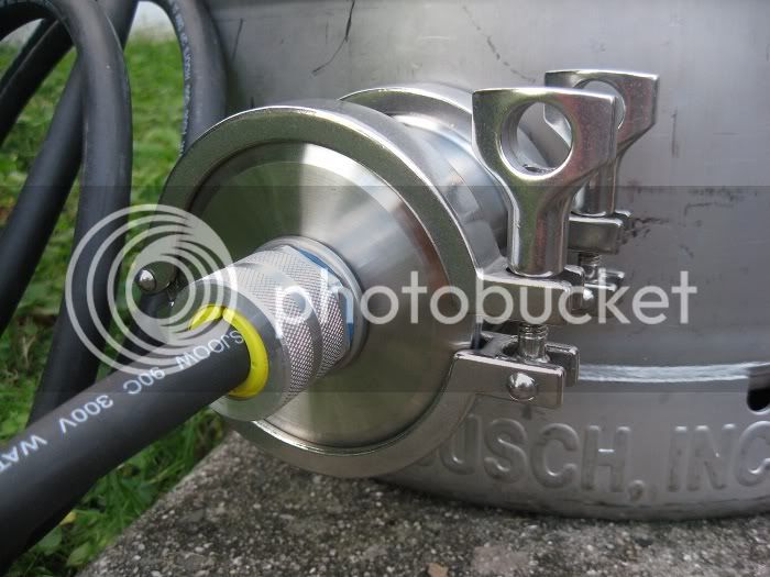
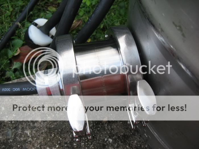
You're capabale of making your own, but I'm looking at a setup on brewershardware.com that's a triclamp housing for the element. Just need to drill the hole in the keg and weld the ferrule to it.
http://www.brewershardware.com/TC15F10NPSCOV.html
That design is nice, but in my opinion, it has one flaw, it is too long.
Even though the first inch of most elements is not heated, I would really think that you want the element as close to having it's base at the Kettle wall as possible.
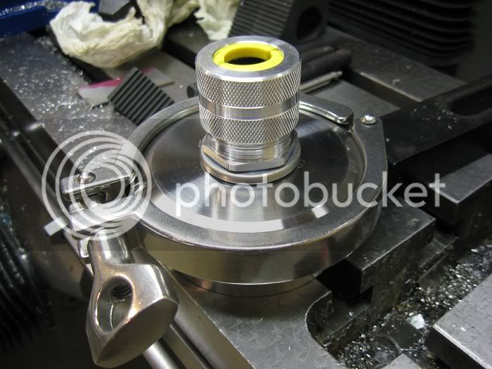
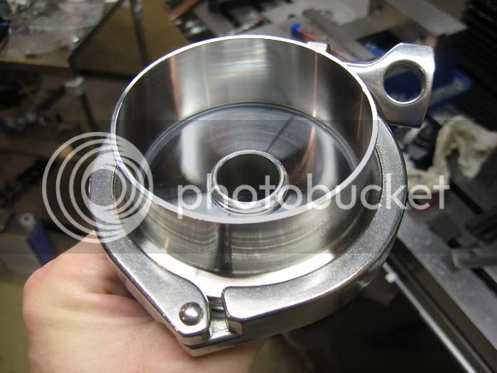
I am looking at using a 2" sanitary ferrule on the keggle, then a recessed cup that the element goes in, and instead of screwing the element in, using a locknut (will not have clearance to be able to get socket in to tighten element) the recessed cup will be welded to another ferrule, and clamped..
-mike
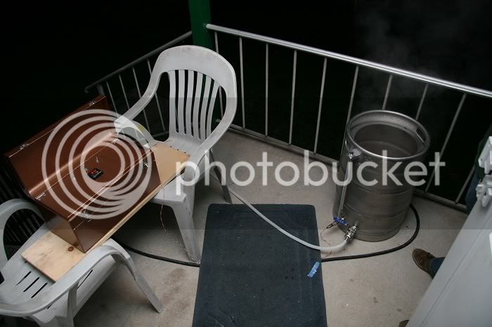
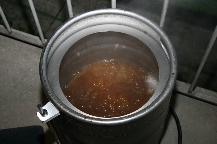
We had an "emergency" electric brew session the other night because we had a lot of wet hops to use. Even though the keggle is not completely finished (I still have to weld up the element housing and add a cord grip to it), I wanted to use it due to the amount of whole hops in the brew. I also vowed never to use an auto siphon again during our last brew session, so we HAD to use the keggle this time.
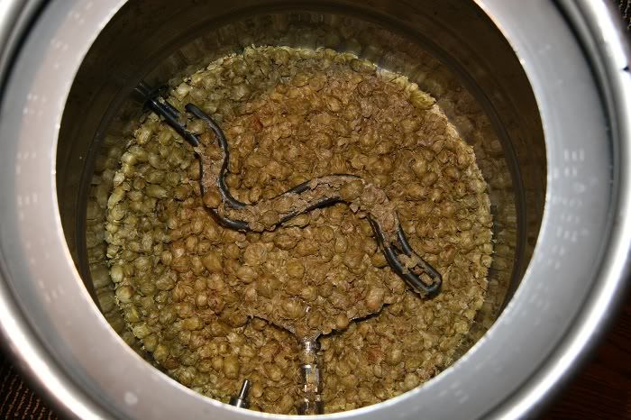
The recipe was a 6 gallon extract with grains IPA with almost all whole hops, wet and dry. We tested boil off with water prior to brewing, so we nailed that (1.5 gallons), but completely blew getting 6 gallons in the fermenter. We ended up with slightly over 5 gallons. I think it's due to all the wort that got held up in the whole hops. We finally nailed the gravity, though, which is something we never did when doing partial boils. I think that was because we also had a lot of wort held up in the hops in the bottom of the old brew kettle and we would always top off the fermenter to 6 gallons. Bad move, but the beers turned out amazing anyway. We decided not to top this batch off because the gravity was right on.
We also used a newly constructed counterflow wort chiller for the first time which worked great even with 70 something degree tap water. No more ice baths!
So, with the exception of getting shorted on the volume, the first brew in the ekeggle was a complete success. There's still a lot that I want to do and change, but it's nice to be able to brew with it in the meantime!
clearwaterbrewer said:That design is nice, but in my opinion, it has one flaw, it is too long.
Even though the first inch of most elements is not heated, I would really think that you want the element as close to having it's base at the Kettle wall as possible.
I am looking at using a 2" sanitary ferrule on the keggle, then a recessed cup that the element goes in, and instead of screwing the element in, using a locknut (will not have clearance to be able to get socket in to tighten element) the recessed cup will be welded to another ferrule, and clamped..
-mike

Any chance of getting a sketch out of a diagram of this? I love this and I can follow some of what's going on just from how neat you did this, but can't quite follow all of it. I've been slogging through the forums trying to find a wiring diagram to use on my single vessel eBIAB that I'm doing and this is the best one I've seen. I'm going pretty basic but also want the option (but not the strict need) to plug a pump in, which you appear to have.
This is so beautiful it brings a tear to my eye. How can I copy it?
This is so beautiful it brings a tear to my eye. How can I copy it?
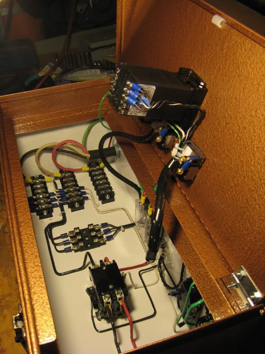
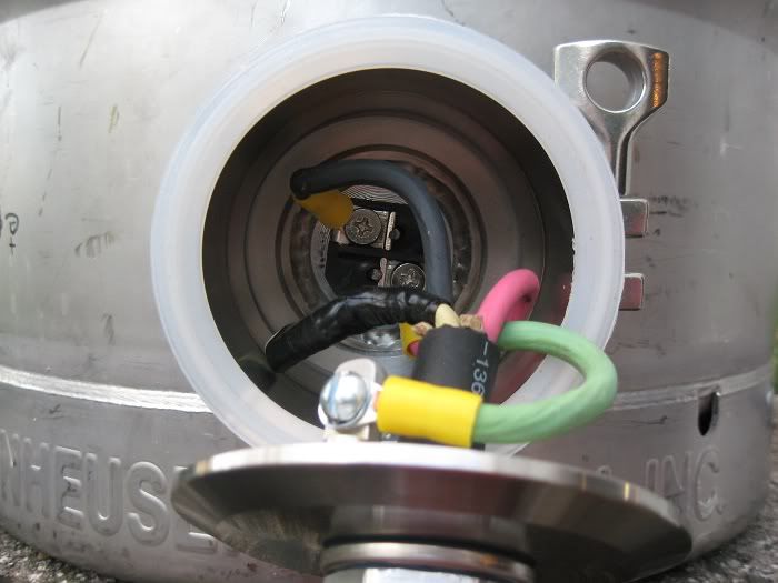
I should be able to hose this thing down and not get a drop of water in there. I'm actually now worried about getting water in the Auber RTD. It seems kind of cheaply made. I think they mean liquid tight from the inside. Well, duh. There's no way that the pins that stick out of the RTD are liquid tight. There's also the seam where the two parts of it are screwed together. It doesn't look like there's any gasket or sealer between the two parts, but I'll have to take it apart to check.
Enter your email address to join: