Control Panel Wiring Question

Homebrew Talk - Beer, Wine, Mead, & Cider Brewing Discussion Forum

Help Support Homebrew Talk - Beer, Wine, Mead, & Cider Brewing Discussion Forum:

This site may earn a commission from merchant affiliate links, including eBay, Amazon, and others.

JMichael

Supporting Member
HBT Supporter
Joined
Jun 1, 2010
Messages
42
Reaction score
0
Location
NC
I have two auber syl-2342 PID controllers, two chugger pumps from usa pumps (same as March 809, got two stainless for $250 here ) and two STC 2w160 solenoid valves.

Here is a drawing of how I believe I should wire everything into a control panel. I'm not an electrician, or artist, but this is what I have figured out by reading threads here and other online forums. Can you guys take a look at this and tell me if this will work? Also, if I wanted to add fuses would that be done by putting the fuse in the neutral line to the object I want to protect?

I thought I would use terminal strips to help keep things organized. I added a small one for a ground since the pumps have three wires. Is my thinking correct on this too?

What kind of testing equipment should I be using to test these connections before plugging this thing into a power source?
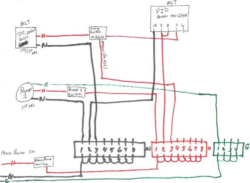
my Brewstand wiring.jpg
 
I have two auber syl-2342 PID controllers, two chugger pumps from usa pumps (same as March 809, got two stainless for $250 here ) and two STC 2w160 solenoid valves.

Here is a drawing of how I believe I should wire everything into a control panel. I'm not an electrician, or artist, but this is what I have figured out by reading threads here and other online forums. Can you guys take a look at this and tell me if this will work? Also, if I wanted to add fuses would that be done by putting the fuse in the neutral line to the object I want to protect?

I thought I would use terminal strips to help keep things organized. I added a small one for a ground since the pumps have three wires. Is my thinking correct on this too?

What kind of testing equipment should I be using to test these connections before plugging this thing into a power source?

First - ALWAYS fuse the HOT wire. And I'd fuse each component coming from your main feed, as well as the main feed itself.

Your 3-way switch is actually a 2-way switch in your drawing. It connectes the valve to either the PID or the power.
I would make it a 3-way switch - "ON - OFF - PID"
As you have it drawn, if the PID says the valve should be on, you have no way to shut it off! That could get hairy in a hurry if something is going wrong.

Edit - Never mind - I see it now!

For testing, Put a meter where the valve is supposed to go, and where the pump is supposed to go. Make sure that power is there when you think it should be before you hook it up to the gas.

I'm no expert - So take all that FWIW ;)
 
Another "non-expert" input:
Logic looks good to me.
As mentioned, make sure everything is properly fused and grounded.

Edit: I'm not familiar with that Auber PID... put assuming it is wired correctly, then logic looks good.
 
Another "non-expert" input:
Logic looks good to me.
As mentioned, make sure everything is properly fused and grounded.

Edit: I'm not familiar with that Auber PID... put assuming it is wired correctly, then logic looks good.

I checked - OP's got it right...
 
Thanks for the response guys. Hopefully, I'll have time to work on this some tonight. Not too much more left to do to get brewing on the new system.
 
What type of fuse block of fuse holders should I look at? In line, single, block? What amp volts?

Volts * Amps = Watts

So a 5500 watt element at 220 volts will draw 5500/220=25 amps.

My 110v March 809 says 1.4 amps on the motor, so I would install a 1.5 Amp Slo-Blow fuse or breaker.
I don't know the specs on the valve, you'd have to look them up. It'll give you the information you seek ;)
 
Jmichael,

If you haven't already, Please read:

https://www.homebrewtalk.com/f51/electrical-primer-brewers-145019/

Make sure you have a good grasp of what you are doing and WHY you're doing it, before you start wiring things up.

Please don't take offense but some of your questions make me a bit nervous.

IMO, you have a decent drawing to start with from a logical perspective.

Sizing the components/wire and proper intallation is critical. If done incorrectly, best case; you damage the equipment, worst case; you electrocute yourself (or someone else), or cause a fire.


No offense taken. I have very little experience with electical wiring. Trust me, I won't even cut a wire, or attempt to put power to anything until I at least half way know what I am doing and why. That's why I'm asking questions.
 
Volts * Amps = Watts

So a 5500 watt element at 220 volts will draw 5500/220=25 amps.

My 110v March 809 says 1.4 amps on the motor, so I would install a 1.5 Amp fuse or breaker.
I don't know the specs on the valve, you'd have to look them up. It'll give you the information you seek ;)


Thanks SweetS.

The volts are listed on both the pumps and the valves but I couldn't find the amps listed anywhere. The PID documentation tells what fuses to use. I don't have the docs infront of me right now so I can't quote what amp but they do say use a slow burning. Although, I did read in the primer thread (I think) that the fast burning fuse should be used instead. So, I'll need to look at that a bit further.
 
I have two auber syl-2342 PID controllers, two chugger pumps from usa pumps (same as March 809, got two stainless for $250 here ) and two STC 2w160 solenoid valves.

Here is a drawing of how I believe I should wire everything into a control panel. I'm not an electrician, or artist, but this is what I have figured out by reading threads here and other online forums. Can you guys take a look at this and tell me if this will work? Also, if I wanted to add fuses would that be done by putting the fuse in the neutral line to the object I want to protect?

I thought I would use terminal strips to help keep things organized. I added a small one for a ground since the pumps have three wires. Is my thinking correct on this too?

What kind of testing equipment should I be using to test these connections before plugging this thing into a power source?

Your diagram looks fine to me.
 
The pump has a current pulse when it starts up - so you use a slo-blo fuse or it will be popping every time it starts. Since you are mixing wiring and plumbing you should use a GFI circuit to immediately interrupt the circuit if it senses a fault to ground (spend $15 and save your life).


Watts = volts times amps so if you know the wattage of the motor, you can figure the amps it will draw. It will draw more when it starts - these are running amps.

+1
Edited the original post - Use a slo-blow fuse for any inductive load.
 
Back
Top