Fishdisease
Member
Hi Everyone,
Well, after careful consideration and an irrational need to always to building and improving my system, I've decided to go electric. But first...
I've been brewing for about 12 years, seriously for about 3 and AG for the last 2. About 6 months ago I moved from stove-top 5 gallon to a 10 gallon BK / cooler MTL. One thing lead to another and here I am, upgrading my system to a Brutus 10e style system. I've almost acquired everything I need, I've got everything for the mechanical side of the build, just waiting on a few electrical details.
I'm going to do a Kal inspired control box, as most of the ones I've seen are, and a 2X 4500W single tier, 3 vessel system. I will eventually move into a HERMS system, but if I want to be brewing on this new electric system by Xmas (my goal), I'll need to build in stages (due to the lack of available financing from SWMBO). So for now, I'm simply going to insulate my MLT keg with Roxul for heat retention and see how it goes. I've always got my cooler MLT to fall back on if the insulation is not sufficient. I've got 2 50L Euro Sankes for my HLT and MLT and a 58L Sanke for my BK. I'll be cutting the bottoms and using tri-clover fittings for the drains.
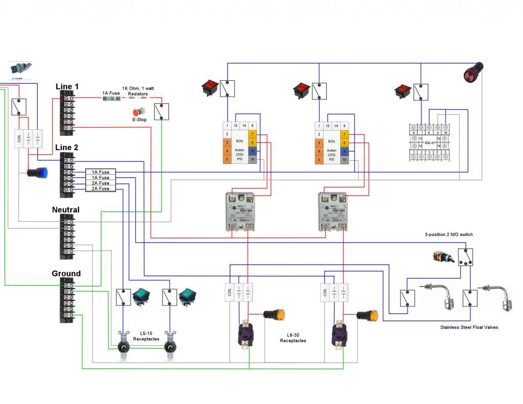
So, last night I decided to go ahead and start the control panel (mostly figuring out design). I'm still working on the wiring diagram and I very much open to suggestions, but I'm not in a rush or completely set on the design (until I cut the holes in the control panel!).
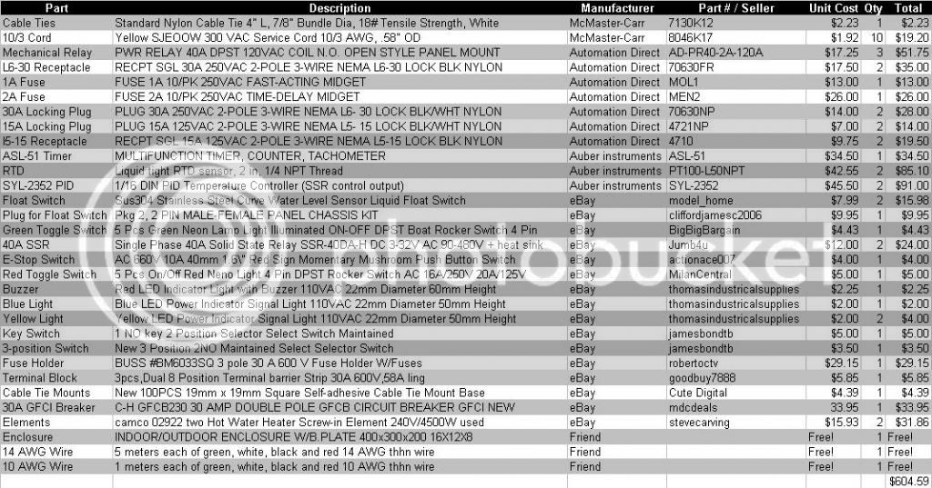
Here's what I have to start with:
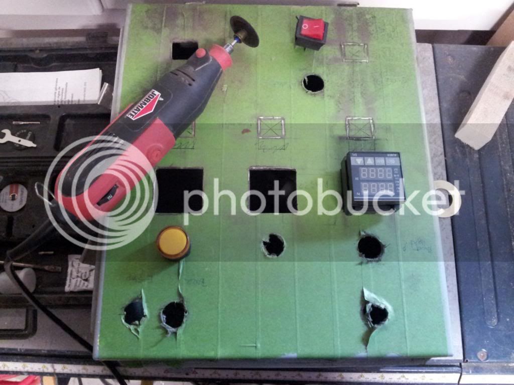
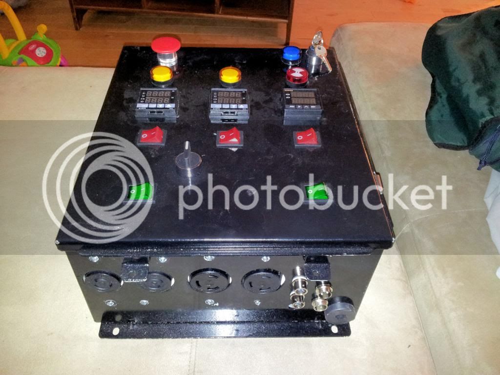
And here's the layout for the control panel:
So I'd appreciate any thoughts, comments, and pointers moving forward. I've learned a lot from spending far too much time reading this forum, but I'm no expert. Thanks
Well, after careful consideration and an irrational need to always to building and improving my system, I've decided to go electric. But first...
I've been brewing for about 12 years, seriously for about 3 and AG for the last 2. About 6 months ago I moved from stove-top 5 gallon to a 10 gallon BK / cooler MTL. One thing lead to another and here I am, upgrading my system to a Brutus 10e style system. I've almost acquired everything I need, I've got everything for the mechanical side of the build, just waiting on a few electrical details.
I'm going to do a Kal inspired control box, as most of the ones I've seen are, and a 2X 4500W single tier, 3 vessel system. I will eventually move into a HERMS system, but if I want to be brewing on this new electric system by Xmas (my goal), I'll need to build in stages (due to the lack of available financing from SWMBO). So for now, I'm simply going to insulate my MLT keg with Roxul for heat retention and see how it goes. I've always got my cooler MLT to fall back on if the insulation is not sufficient. I've got 2 50L Euro Sankes for my HLT and MLT and a 58L Sanke for my BK. I'll be cutting the bottoms and using tri-clover fittings for the drains.
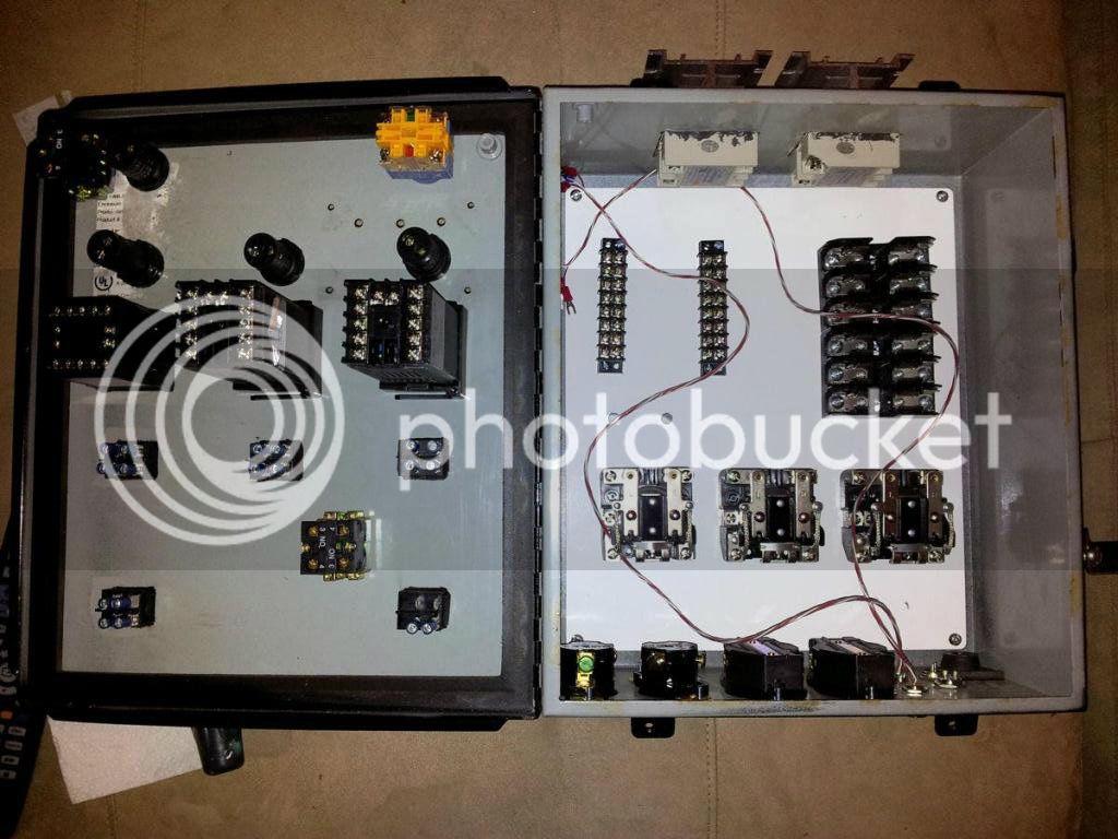
So, last night I decided to go ahead and start the control panel (mostly figuring out design). I'm still working on the wiring diagram and I very much open to suggestions, but I'm not in a rush or completely set on the design (until I cut the holes in the control panel!).
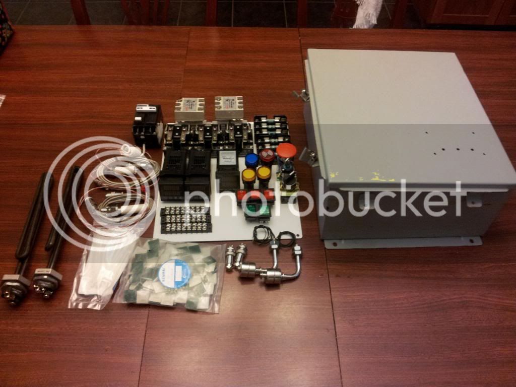
Here's what I have to start with:
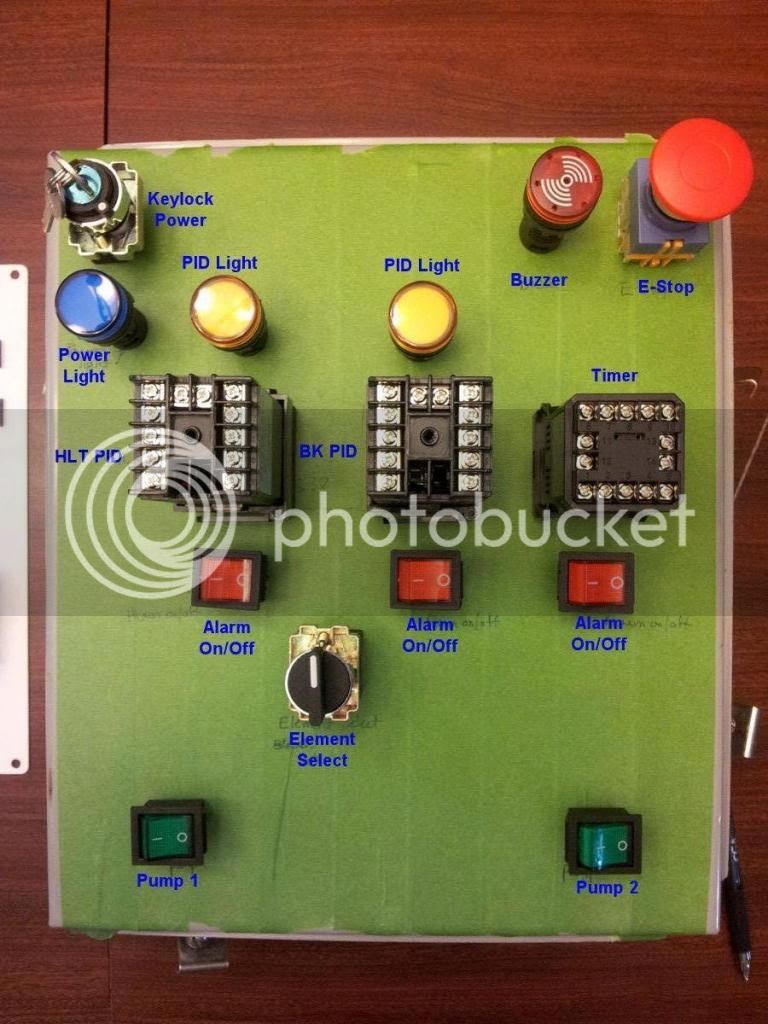
And here's the layout for the control panel:
So I'd appreciate any thoughts, comments, and pointers moving forward. I've learned a lot from spending far too much time reading this forum, but I'm no expert. Thanks