led indicator lights

Homebrew Talk - Beer, Wine, Mead, & Cider Brewing Discussion Forum

Help Support Homebrew Talk - Beer, Wine, Mead, & Cider Brewing Discussion Forum:

This site may earn a commission from merchant affiliate links, including eBay, Amazon, and others.

Lost

Well-Known Member
Joined
Aug 2, 2005
Messages
594
Reaction score
7
Location
Tampa
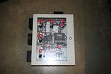
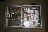
I'd like to put a couple led indicator lights in the control box I'm building. I'd like to source it locally (and cheap) from radio shack.

I need a led on the DC line from my PID to my SSR to tell me when the PID is applying power to the elements. Then I think I'd also like a led on one or both of the hot legs going to the 240v 5500 watt elements so I know when the element is actually being powered (to keep me from leaving the PID on with the cutoff switch off). And maybe one more on the 120 line going to the single pump.

I'm working from the diagram P-J drew up in this thread (the first diagram with the contactors). https://www.homebrewtalk.com/f170/simple-eherms-following-pjs-diagram-w-only-1-pid-221403/

I think I only need a led on the hot leg of the element that is powered by the contactor. The other hot leg will be on if the SSR tells it to be and I can see that with the led on the dc line feeding the SSR (of course this assumes that the SSR is working correctly).

So really I need a wiring diagram for the PID output to SSR and one for the 120v lines for the pump and one leg of each element.

From what I've gathered I just need a resistor for the DC current to bring the input voltage to the correct level for the led. So the resistor and then the led are wired in parallel to the line going to the SSR. I think. The PID output is a 12v DC 30mA according to Auber's manual for the 2352 PID.

For the 120AC lines I'm more confused. Evidently the reverse polarity that occurs when the AC line alternates will destroy the led so a capacitor or bridge is needed in addition to the right resistor. But I have no idea what a capacitor or bridge looks like or how to wire it up correctly so I don't set my control box on fire.

I may forego the fancy lighting if this ends up being more work than it is worth.
 
unfortunately you cant directly power a LED with alternating current. why not just get some indicator lights that run on AC? im sure radio shack has some. otherwise you would need a rectifier to essentially make a mini power supply for the light.

for the SSR LED, all you need is a resistor between (+) and the LED, then the other leg of the LED goes to (-) (be careful which leg is which, the only work one way. normally the long leg is +, the shorter one -).

you want to make sure you get an LED with power requirements low enough that it doesnt suck up all the juice and cause the SSR not to get a signal. you have 30mA to work with, so the [power requirements of the LED] + [minimum trigger current] of the SSR has to be less than 30mA combined.

the value of the resistor depends on the operating voltage of the LED, and the DC voltage being supplied to it (12V). the info can be found in the spec sheet for the LED.

http://ledz.com/?p=zz.led.resistor.calculator
 
I'd like to source it locally (and cheap) from radio shack.
These two things ("radio shack" and "cheap") are mutually exclusive. Their prices on components are pretty steep compared to buying online from a place that specializes in components. Radio Shack is pretty much just an AT&T store these days, with some other random things on shelves.

but... you CAN get the things you want there.

I think I only need a led on the hot leg of the element that is powered by the contactor. The other hot leg will be on if the SSR tells it to be and I can see that with the led on the dc line feeding the SSR (of course this assumes that the SSR is working correctly).
Yeah, that will work. The one attached to the AC line will be your "element armed" light and the on the DC signal from the PID will be the "element firing" light. When both are on, you are getting heat.


From what I've gathered I just need a resistor for the DC current to bring the input voltage to the correct level for the led. So the resistor and then the led are wired in parallel to the line going to the SSR. I think. The PID output is a 12v DC 30mA according to Auber's manual for the 2352 PID.
Radio Shack sells LED "assemblies" that are packaged up, panel mount things that contains both the LED and a current limiting resistor in one module. Just get one of those and hook it in parallel to the SSR control signals and you'll be good to go.

For the 120AC lines I'm more confused. Evidently the reverse polarity that occurs when the AC line alternates will destroy the led so a capacitor or bridge is needed in addition to the right resistor. But I have no idea what a capacitor or bridge looks like or how to wire it up correctly so I don't set my control box on fire.

They should have panel mount neon indicator lamps in the store. These will run off 120VAC directly. No messing around with trying to build a rectifier to convert high voltage AC into low voltage DC. That's way more trouble than it's worth.
 
Just confirming what others have said. Use traditional AC pilot lamps for your high-voltage side indicators. Fair warning even neon ones may give you issues though depending on their current requirements. A properly functioning SSR will still leak a few mA - enough to light some neon lamps.
 
Hey - piggybacking on this thread ...

So I ordered three of these a few weeks ago: http://www.ebay.com/itm/11072554384...AX:IT&_trksid=p3984.m1423.l2649#ht_1966wt_899

Can I just wire them in parallel to the SSR control lines, or do I need to put resistors somewhere in there? I'm using 120v all the way through (2 circuits, 2 elements, 1 PID). Basically it's just a 120v circuit to an element, with a switch between the power in and the SSR. Can I just wire these to the switch, along with my 120v line?

My radio shack LED's popped the first time I turned my box on, so I either bought the wrong product or wired them in wrong.
 
I forsee problems running the LED and the SSR off that 30mA supply. I would just use indicators to show when the elements are on, seeing that that's all you really want to know anyway.
 
Sorry, realized that I didn't mean the SSR control lines. I meant the lines that are providing power to the element (and are therefore passing through the SSR). Want to put indicator lights in-line to show whether the elements are being powered or not.


me bad at terminology. :(
 
Radio Shack sells some neon bulbs for 120v circuits. http://www.radioshack.com/product/index.jsp?productId=2062374

They work directly on 120v and will work in series with a 100k resistor on 240v. I know, they're not as high tech as LED's but they are cheap and don't require any support circuitry.

I am using these on the output of the SSR's to indicate when the elements and pumps are operating.

Yeah, I do something similar. The lamps I got needed only 50kOhm resistor in series with them to drop half the voltage, but I then connect them in parallel with the heater element on 240V. That lets the indicator lamp only illuminate when there is really heat being applied.
 
I tried to hook up 110v lamps to the SSr output and anything more than 1 lamp triggered the GFI.. lamp leaking to ground makes GFI breaker trip
and the Aurber PID didn't have enough current for 12v LEDs (3)

ended up installing independent contact blocks for the lamps at the switches and ran them off a non GFI 110v circut
 
Henrythe9th said:
I tried to hook up 110v lamps to the SSr output and anything more than 1 lamp triggered the GFI.. lamp leaking to ground makes GFI breaker trip
and the Aurber PID didn't have enough current for 12v LEDs (3)

ended up installing independent contact blocks for the lamps at the switches and ran them off a non GFI 110v circut

Why do you have the lamp connected to ground?
 
220 v lamps coming off the switched leg of the SSR wouldn't have worked any way as the SSR leaks 40volts
everything is 220v except 1 110v circut for a small pump i'm using a gfi outlet for it off a 20 breaker


4 5500w ULD elements 5 BBL boil pot switched 220v CIP pump and switched 110v recirc pump
 
220v lamps coming off the switched SSR lines will work fine. SSRs leak current, not voltage. They leak a very miniscule amount of current, too. Your multi-meter might show it as 40V, because the meter needs very little current to register a voltage.

When the current leaks through the SSR, it will see two paths that it can go on. One is the lamp and the other is the heating element. Current favors the path of least resistance, which is the heating element in this case (a few Ohms on the element, tens of 1000's of Ohms for the lamp). The vast majority of the leakage current will go through the heating element and your light will work exactly like you want it to.
 
Back
Top