Wiring assistance - single PID/SSR single kettle setup

Homebrew Talk - Beer, Wine, Mead, & Cider Brewing Discussion Forum

Help Support Homebrew Talk - Beer, Wine, Mead, & Cider Brewing Discussion Forum:

This site may earn a commission from merchant affiliate links, including eBay, Amazon, and others.

Psych

Well-Known Member
Joined
Mar 17, 2011
Messages
778
Reaction score
41
Location
Kelowna
Wondering if anyone has a wiring diagram to suit this that they could show me? Setup will be:

240v 4-pin dryer plug outlet (30amp breaker) to one of those 17 foot 8 gauge wire dryer cords with a 30amp gfci built into it (Ebay). That will feed into my control box and the wires will connect directly to something, ie: no plug on that end. One Auber PID controlling a 40amp Auber SSR w/heatsink. One thermoprobe to kettle.

This will run a 4500watt element, and everything will be done in a single kettle. Brew in a bag (BIAB) style mostly, I'm thinking. No pumps or anything like that.

I want a light in there indicating if the element is on, and would like a switch to flip to actually turn the element on, separate of power to the PID. Need to be able to monitor temps in the kettle using the PID without having the element on.

I'm limited on budget for this but already have the kettle, PID/SSR/thermoprobe and a usable steel box. I'd like to go as cheap as possible while still being safe :)

Thanks so much, amazing how much I didn't think about when I first figured I'd put an element in a kettle and just heat water up :drunk:
 
I've not been able to find one that is this basic...no pumps, no timers, no alarms. I need one indicator light and one toggle switch to fire the element up, then pid and ssr so keep it rolling.

I'll keep looking though, search terms eluding me so far :)
 
Woo! Many thanks PJ, really appreciate it! So those terminal blocks off of the main 240v incoming line, are those basically like a 'plug main wire in and it shares that out to each of the rest of the terminals on the same block' sort of deal?

So could I run the e-stop switch's line2 wire from one of the other terminals on the line2 block? Similarly with the light, could I run that off of the neutral line and install another block to the one side of the ssr?

Just confused on how to mate wires or split them in this situation :)
 
Great! Thanks again, parts are in the mail and the little bits will come from local shops, figure I'll build my own brewstand with some scrap lumber I have kicking around.

Things are lining up!
 
Wish I had some, but still waiting on parts from Auber...two weeks in the mail now, hopefully if they come in this week I'll have something to show by next week :)
 
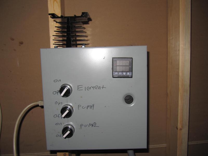
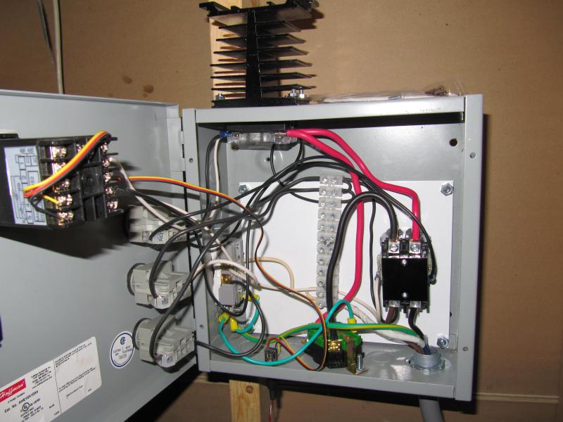
Figure id share my very similar panel with a fellow BCer. I unplug the HLT to hook up the BK when i start my sparge. And yes my writing just is that horrible. One day ill toss in the other switch i have to control the element and controller independently.

IMG_2394.jpg


IMG_2395.jpg
 
Nice, this is definitely similar! What's the white material that you mounted everything onto?
 
Its just a steel backing plate, probably didnt need it, but its there now. Oh btw, the logic on the PID is pretty retarded. I read a post about how its really not meant for what we do, i havnt done it yet but theres a few parameters in the controller that can be changed to make it smarter.
 
That's good to know for sure. I actually bought the 2362 PID as it seems to offer some other function for kiln controlling, something SWMBO may be getting into in the future.

So steel, I guess it's fine to mount all of this stuff right on metal, everything is all insulated and such (like the terminal blocks and switches and such)?
 
Ya absolutely, each component has something to mount with thats completely insulated. And the box is grounded so if theres a problem the GFCI pops.
 
A little OT, I dont know where you're getting your grain, or how much you're paying. But if you think ull be able to brew 5, 5 gallon batches in the next 6 months, its well worth to talk to grambrinus in armstrong, they sell 55lb sacks for $22 and they dont care who you are. You may also have success getting bulk grain from your local brewery/brewpubs for ussually around $30 a sack, with the side bonus that they might sell you hops for cheap.

One more thing, if you ever do extract again, Oakanagan brewhouse sells it for $6/liter last time i was there.
 
That's funny, I just found Okanagan Brewhouse about a month ago! Their LME is up to $8.50/L but it's still a good deal I figure.

I am doing all grain now though (a big one batch in, but more should be coming) and recently heard of Gambrinus selling for that price to anyone. Definitely getting base malts there from now on. Can't pass up that price, direct from the manufacturer!

Thanks for the tips, totally appreciated!
 
Related to this thread, the 240V DPST switch between the SSR and the Element, I can't find anything like that (no surprise, seem to be unable to find anything locally without massive digging, hehe).

Is there a way to rig a 'turn the element on' switch by only using one leg of the hot lines? So I could find just a 120V 25amp switch, which I CAN find?

I'll ebay one if needbe but wanted to explore other options as well :)
 
Jackpot! Nice, thank you!

Yeah that's perfect, easy to mount and 20amps is fine I think. You don't need to do the 80% rule for switches and amps, do you? Like I can use this 20amp rated switch to turn on/off an 18.8amp circuit? Cool though, that's nice and economical!
 
I have used one on a 4500W element for 15 brews with hour-long boils with no issue. It might be wise to have a fuse somewhere along the line, but I don't…
 
Just wanted to mention here that my kettle has been successfully electrified, in a good way! I'll be doing a proper post with pictures (shame I never took any build pics) but basically one pid, one SSR, using PJ's diagram without the e-stop or the light (as I forgot to wire it...). Massively ugly disconnect box as the DPST switch for the hot lines, instead of a nice toggle switch (sigh...Canada...).

But it freaking works! I threw in 2 or so gallons of water as a test run, plugged in the element to my box-o-electricity and blam, started hearing the sounds of water suddenly get HOT! Took very little time to get to 150F and not much longer to get to boiling.

Downside is my RTD is a bit off, should have gone with the 4 inch I guess. I'll figure it out though, just need it accurate around the 150 range.

SO stoked that I didn't fry myself, everything worked on mostly the first try, everything is grounded and GFCI'd, and some of it even looks sort of cool!
 
Hi, new to the forum, great stuff here! I've been planning an electric brew kettle for a while now. PJ's single kettle controller is the best looking, least complicated plan I have come across thus far. The only part I don't quite understand is the e-stop leg of the circuit. Can someone please explain how the e-stop works. Is the switch open and channels current to the ground when closed to pop the breaker? What does the fuse do? Thanks!
 
The E-Stop is specifically set up to act in the same manner as the test button on the GFCI breaker. It provides a small leakage current to equipment ground which activates the GFCI and kills all power being delivered to your panel. The 1 amp fuse is there to protect the wiring and the switch. The two 1K ohm resistors are to limit the current flow.

Please keep in mind that you must protect your electric brewery with a GFCI mains breaker. Without it you are playing "You bet your life."!
 
Thanks for the quick reply! Yeah, I intend on adding as many safety features as I can on playing with this much juice. Much clearer on the e-stop, thanks again, great forum!
 
By the way, would it be better to use a GFCI breaker in my main fuse box or a GFCI protected outlet to plug the control box into or both?
 
Depending on your mains panel - it might be far less expensive to pick up a Spa Panel from HomeDepot and wire it in before your brewery. Something like this:

power-panel-5a.jpg


HTH
 
With this wiring isn't the element always on as long as the switch for it is on? Or does the element not work with only 120v?

Also I don't understand the purpose of the PID in any of these wiring diagrams. Aren't relays on/off switches? So isn't the PID effectively acting as a thermostat as opposed to a PID controller?
 
Thanks for that.

Psych,

I didn't have one that exactly fit your description so I made this one up for you:
(Click the image for a full scale diagram that can be printed on tabloid paper 11" x 17")


Hope this helps.

Nice diagram! I work at an electronics company and im innt he process of engineereing a one off system with programmable logic control, with the ability to store profiles for mash temps and sparge water tems along with audible timers. its sun beleivably simple to build these setups, if you can read a road map than you can follow a diagram and safely make your connections! cheers!
 
With this wiring isn't the element always on as long as the switch for it is on? Or does the element not work with only 120v?


There are 2 switches...one for the PID and one for the element.

Also I don't understand the purpose of the PID in any of these wiring diagrams. Aren't relays on/off switches? So isn't the PID effectively acting as a thermostat as opposed to a PID controller

That is exactly what it is used for. The PID measures/regulates temp and sends the appropriate instruction to the SSR (an electronic switch) to power the element on and off.

John
 
the element will work on 120v just figure on more current. divide your watts by voltage =approx amperage.
 
There are 2 switches...one for the PID and one for the element.

Right. And if the switch for the heating element is on it is always at half power. I just wasn't sure why that is the case as opposed to the PID controlling all the power to the element. Basically the PID can't turn the element off.

That is exactly what it is used for. The PID measures/regulates temp and sends the appropriate instruction to the SSR (an electronic switch) to power the element on and off.

But a PID takes a variable input and creates a variable output. Hooking it up to a relay means you can only turn the power on or off, no where in between. Or at least that is my understanding of what is going on. The PID will definitely work but it seems to me to be acting more as a thermostat not a PID. The only reason I ask is because thermostats are cheaper and simpler.

My understanding of this wiring (which definitely could be incorrect) is that the heating element is either at half power or full power. It can be used to control temperature just not as well as it seems like it could.
 
The SSR cuts off one leg of the power with one leg disconnected there is no more current flowing through the heating element.

The percentage delivered by the PID is from a rapid switching on and off of the SSR thats why it cannot be a mechanical relay because they cannot stand that many cycles. In other words if you are set at 70% the PID turns the power on 70% of the time.

Hope that clears it up some.
 
The SSR cuts off one leg of the power with one leg disconnected there is no more current flowing through the heating element.
Uh. I still don't understand how this works....

The percentage delivered by the PID is from a rapid switching on and off of the SSR thats why it cannot be a mechanical relay because they cannot stand that many cycles. In other words if you are set at 70% the PID turns the power on 70% of the time.

Ok so it's controlling duty cycle not voltage or current amplitude.
 
Uh. I still don't understand how this works...

Ok. Question for you. If you have a light bulb with only one wire (the hot wire) attached to it, will the bulb light up? I think not as there is no path for the electricity to flow. The same thing applies to a SSR. The SSR is, after all, a "Solid State Relay". When the SSR is not told to conduct electricity, there is no currect path and thus no current flow.

I do not know how else to explain it to you.
 
I think hes trying to ask if you can run the element at various amounts of current(maybe thinking its how temps are controlled?) The PIDs we use at my shop have a 110vac power supply and a +3vdc output for switching the relay. You set desired temp, the tmp sensor senses current temp and the relay is switched on. Once temp is reached its circut opens and only closes momentarily when needed to maintain or raise temps. Sounds like he thought that you could run it on one leg of the 220 (you could if you went 1 leg and ground) to heat up slower. Poor idea less efficient not as safe in my eyes

Sent from my MB502 using Home Brew Talk
 
We usually set switchin cycles to 100% (always on) unless the equipment under test requires a certain gain or loss of degrees per minute then well set the cycle accordingly

Sent from my MB502 using Home Brew Talk
 
I think hes trying to ask if you can run the element at various amounts of current(maybe thinking its how temps are controlled?)

If this is the case, this is easily done by putting the PID in manual mode and setting the Sv to the % of output. I do this for my boils now (thanks to P-J) and set it to 69% rather than 212F.

John
 
Back
Top