Electric Noob starting E-brewery. Help pls!

Homebrew Talk - Beer, Wine, Mead, & Cider Brewing Discussion Forum

Help Support Homebrew Talk - Beer, Wine, Mead, & Cider Brewing Discussion Forum:

This site may earn a commission from merchant affiliate links, including eBay, Amazon, and others.
Actually I completely disagree. Do not connect it that way. The nec doesnt address this for 120/240 volt systems, but this is common on 120v circuits and the really no different. Bascially just remove the jumper from the neutral bar to the ground bar. Installing a gfci does not give you a ground. It does give you ground fault protection. That little jumper can create a very hazardous senario and not lot allow the gfci to work properly if you were to lose the neutral going back to the panel.
Missed your post when you did it.

IF you are referring to the post I made before your 'reply': You do not have a clue. Go ahead and quote the ' NEC code' all day long.
 
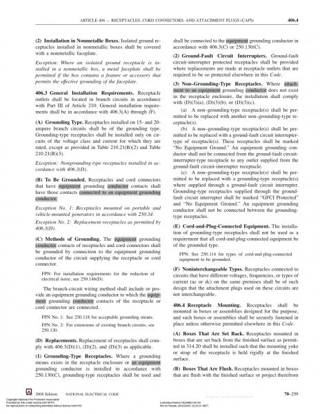
Pj you are dead wrong, you really shouldn't be giving people advice on things you are not curently up to date on. This electrical stuff can kill people you know. Attatched is the page out of the 2008 NEC code book saying not to do what you are telling these folks to do. I may not have the graphic desgin skills to whip together fancy diagrams, but I do my my basics of electrical grounding and bonding. At no point besides the "first means of disconnect", ie main breaker. Do you ever bond a neutral and ground. Ask any electrician worth his wire nuts and he'll tell you the same thing. Ground fault protecting a ungrounded 3 wire 30a circuit you plan on brewing beer with is a good idea. What it does not do is give you a equiptment grounding conductor. The only way to get a ground is to run a ground wire.
grandequeso

National Electrical Code -2008 Edition.jpg
 
Earlier in this thread it is mentioned that the feed is a 3 wire 30a, not a 4 wire. Its ok to go 4 wire post gfci protection, it not ok to bond the neutral to the ground.
 
Earlier in this thread it is mentioned that the feed is a 3 wire 30a, not a 4 wire. Its ok to go 4 wire post gfci protection, it not ok to bond the neutral to the ground.
Well apparently you are not aware of the way clothes dryers and electric ranges were set up pre 2002 code changes. Or for that matter how a power feed is delivered to a barn and then setup for 240-120V power.
 
Well apparently you are not aware of the way clothes dryers and electric ranges were set up pre 2002 code changes. Or for that matter how a power feed is delivered to a barn and then setup for 240-120V power.

If the 3-wire 240 is properly wired, there is no neutral. It's 2 hots and a ground.
If you have 3 wire 240 with neutral, it's not grounded at all.

That's a little scarey isn't it?

Yea, after revisiting the drawing, it's scarey.
Where's the ground? After the GFI, you have 4 wire 240 with neutral and ground. Except your ground isn't a ground! It's neutral. That literally means you will become the ground, if given the opportunity.
This is a bad idea, sorry PJ.
There HAS to be a ground in this rig, or it's just plain dangerous. With current on neutral, and neutral tied to ground, and ground connected to your ****, if you touch the metal and you become the ground VIA wet floor/feet, you're gonna get shocked.

Unless you actually have a ground somewhere I'm missing. In which case, the neutral and ground shouldn't be connected at the spa panel...
 
Pj- things change, safety regs are written in blood. Sure old ungrounded 3 wire dryer circuits were bonded at the frame, their neutral load is inconsequential as it is solely controls. Besides that the code allowed it. When you start connecting pumps that pull neutral loads rated in amps.... Danger zone.

A properly wired three wire system protected by a gfci can still be considered safe. the gfci will (should) trip in milliseconds. Basically before you even felt it. What the gfci does not do is give you a ground. Just ground fault protection. Having a ground path surely would be better, but not necessary if properly protected.
 
I know the neutral and ground are tied at the main panel. But last time I checked, that's the only place you're allowed to do that, according to code. Neutral is supplied as the preferred path for return current, and the ground is a safety backup path in case the neutral fails, or a hot wire is somehow faulted to the chassis. Without that safety, YOU become the backup path.

This is one of those grey areas where advice is worth everything you paid for it. If nothing else, we're talking about setting something up that doesn't meet current electrical code. That literally means that if there's a failure and a fire (Or worse), your insurance will tell you to climb a tree.

You'll probably be fine. But, if it were me, I'd have 2 options:
1) Wire the 3-wire 240 properly. 2 hots and a ground. Get my 120v from a normal receptacle nearby and run the pumps and controls from that.

2) Pull in a ground wire from the main panel, move the spa GFI there, hook everything up according to the diagram with my new 4-wire 240 volt circuit.

Tying the neutral from the panel to ground at the spa panel is just strange to me. It's still a neutral, it's just green now.

Yes, it was legal until what, 1997? Yes, it will probably be fine (As long as your neutral wire is in tact between the GFI and the equipment).
There's a good read here (Same argument, and still worth everything you paid for it)
Specifically posts 10, 16, and 18.

Ever leaned up to a display case at a store and gotten a tingle from the metal parts? This is exactly why that happens.

Another good read and explanation here:

Look, It's not like it should kill you if you do things this way. It probably never will. I'll probably never get hit by lightning or win the lottery either. It doesn't mean I want to go golfing in a thunderstorm, or operate marginally wired high current electrical systems full of water in flip-flops.

Ground your ****
 
2) Pull in a ground wire from the main panel, move the spa GFI there, hook everything up according to the diagram with my new 4-wire 240 volt circuit.

This is what my electrician and I are working on. I'll get some photos in here once we're done.
 
Well apparently you are not aware of the way clothes dryers and electric ranges were set up pre 2002 code changes. Or for that matter how a power feed is delivered to a barn and then setup for 240-120V power.

In trying to be a peacemaker, I'm wondering if both of your are right if viewed from different angles.

I don't know the NEC code, but I was trying to understand how the idea of creating a 4-wire circuit from a Spa Panel that's connected to a 3-wire Dryer outlet would be grounded. Somewhere in the Electrical Primer I read how appliances such as dryers and ranges got away with a 3-wire plug because the appliance is the ONLY thing on the circuit.

In the case of the 4 wire spa panel being "derived" from the 3 wire dryer receptacle, I'm wondering if the "purpose" of this is more to provide "protection" in lieu of a "true" ground.

In the case of this single appliance, the brew rig, that, like a dryer or range, contains both 220V and 110V circuits . . . if something happens that causes current to flow into the green wire in the rig, the GFCI inside the spa panel will detect this within the required amount of time and, as a result, trip the circuit. Even though the green wire between the e-control panel and spa panel isn't a "true" ground, it performs enough of the "function" of a ground wire to trip the circuit should current find its way to ground.

I still may be confused, but in my non-electrician understanding, it appears that grandequeso might be correct in the "strict" sense in that a ground that terminates onto the neutral away from the main panel is not truly a ground according to the Code, yet P.J. is correct in the "functional" sense in that this pseudo-ground wire will serve the purpose of giving the GFCI within the spa panel something to monitor such that if something abnormal happens to shunt current into the ground wire, it will sense it, trip, and thereby protect the brewer.

BTW, another question just hit me: if the spa panel is connected into the 3-wire dryer circuit and mounted outside the house AND you run a wire from the grounding lug inside the spa panel to a piece of pipe stuck into the ground, would you be "truly" grounded?

Respectfully submitted,
Keith
 
in regards to the pipe ground, yes that would work, not if the pipe was stuck in the ground, but yes, if it was a water pipe that was connected to the service ground. Sticking a pipe in the ground wouldn't do jack. The code allows that as a means of obtaining a equiptment ground in a existing structure that does not have a ground available. I really don't see the debate NEC 406.3 (3)c is pretty specific about using gfci on ungrounded circuits where it says "shall be marked no equiptment ground" and "... an equipment grounding conductor shall not be connected" These aren't my opinions, its all in the code book. Any electrical advice I give anyone I can back up with NEC reference as to why or why not it is a good idea. I'm paid quite well to know the electrical code. I'd just feel terrible if some poor bastard hurt himself because he took bad info from the internet. I think the fellas on the mike holt electrical forum would get weeks worth of laughts out of some of the things you see folks telling other folks to do on hbt. All that banter aside anyone in question about anything electrical please contact a qualified preferably licensed electrician.
 
Is the NEC referring to a plug in device though? I thought the NEC was talking about hard wired devices. Maybe I'm wrong.
 
The nec 406.3(3)c that talks about gfci is in reference to ungrounded receptacles, but the theory behind gfci protection is the same.
 
Ok so, my licensed electrician will be adding a 4 prong receptacle to my backyard. He put together this part list:

Electrical Part List.jpg

He quoted me $275 for all the parts. Does this sound reasonable? Or do you guys think i can source these parts cheaper online? If so, where?

Thanks!

-Alex
 
Sounds really decent, that 25' of 10/4 sjo cord isn't cheap. plus a gfci breaker isn't cheap either. along with that its only fair that he marks it up a bit as he has to go out & purchase the stuff and will likely be giving you a warrantee on these items as well. heck at $275 he may not even be marking it up much if at all
 
grandequeso said:
Sounds really decent, that 25' of 10/4 sjo cord isn't cheap. plus a gfci breaker isn't cheap either. along with that its only fair that he marks it up a bit as he has to go out & purchase the stuff and will likely be giving you a warrantee on these items as well. heck at $275 he may not even be marking it up much if at all

Of course that doesn't include his labor as well... Just FYI
 
New additions to the brewery! Will cut holes in them and polish soon.


image-1675256436.jpg


image-3146934360.jpg
 
Just cut up the first keg using an angle grinder and a tube of silicone...


image-158115517.jpg


image-4016786645.jpg


image-3389716683.jpg
 
BeerguyNC61 said:
Did you use the tubing to hold on to the lid?

Not at all. I just used that little piece of cardboard circle to guide me in a circle, I didn't bind it to the angle grinder with a hose clamp or anything, just used my hand (my wrist was extremely tired after this). Once I felt the lid was loose, I simply stopped grinding, gave it a slight tap, and the lid fell right in the keg. One down, one to go :)
 
Another important component in, my enclosure!


image-1573200345.jpg


image-3062640571.jpg


image-2175432432.jpg

It's a 16x16x12 metal enclosure from pioneer breaker. Now I know a lot of people say to stay away from this site, but this is just a metal box, I don't know how anyone can counterfeit that.

I wanted a 16x16x8, but they were sold out and didn't want to wait until November for this. Bigger won't do me any harm now would it? ;)
 
Both kegs cut now, just need to sand down the edges. I think I got a slightly larger cut from today's cut (left), but that doesn't really matter to me. Will post more pics of kegs when cleaned up well and holes, valves, tubes etc. have been made.

image-4174701421.jpg
 
You will be glad for the extra workspace. Mine was upgraded to 20x20x8 and I am really glad.

Hope so! :mug:

Quick question, since im pretty much replicating Kal's build, will any of these SSR's work: http://stores.ebay.com/jamesbondtb/_i.html?_nkw=40a+ssr&submit=Search&_sid=1064500270 ?
Preferably one without a heatsink, im thinking the third one on that list.


I notice on kal's site he recommends output voltage to be 90-480VAC, and the ones on that link are only 24-380VAC, will this be an issue? My heating elements are the "Camco #02963 5500W 240VAC ultra low watt density (ULWD) RIPP element".
Thanks!
 
I don't know for sure as I haven't tried them. I do remember reading several threads where people had problems with ssr products from Ebay. They just didn't hold up.
 
In that case, I'll order them from Auber.

Also, do you all think these relays will work?
http://www.ebay.com/itm/30062983238...l?_sacat=0&_from=R40&_nkw=300629832383&_rdc=1

If not, will any of these work?
http://stores.ebay.com/jamesbondtb/...ubmit=Search&_fsub=2574799010&_sid=1064500270

Thanks so much!

Edit: Reason why I ask about the ones on that first link is because I thought they were a good deal and ordered them impulsively :cross:. Anyways I put the order on hold until i can confirm they work, or so that i can order the proper ones. Thanks!
 
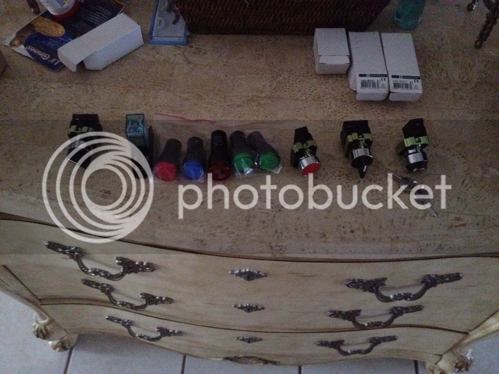
Hey guys, I've been on a temporary hiatus but I'm pleased to say that I am back in business. At this point I have all the parts needed to complete my control panel. Here are some photos of my latest progress.

335F52A5-D017-4602-9ACD-8FA3951215A2-7648-000002AC36CE62C5_zpsa7227870.jpg


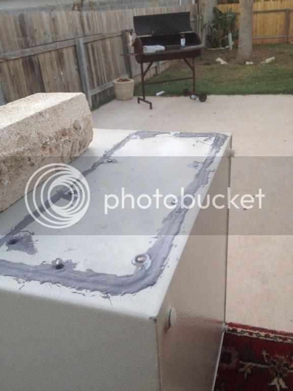
Here is the top part JB welded and the screws sanded down. I just used an angle grinder instead of filing them down.
0568E4DF-41A3-460F-B6FF-C65F6D248E35-7648-000002AC3D944CA0_zpse9132d37.jpg


9F4937F1-44A0-4FDD-BE79-575E37DB8A5F-7509-000002A8995088F6_zps18786a2b.jpg


BF27D395-1D8B-4E16-A1A2-FA947AA69E0E-7509-000002A8A3F527F4_zps915b85ed.jpg
 
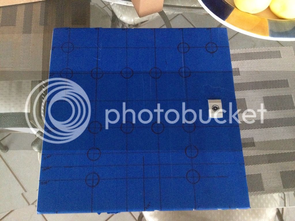
If you haven't drilled them yet, make sure you have clearance for the devices you plan for the two holes in the upper left hand portion of your control panel. It looks like they are very close to the hinges.
 
If you haven't drilled them yet, make sure you have clearance for the devices you plan for the two holes in the upper left hand portion of your control panel. It looks like they are very close to the hinges.

Excellent point. As a matter of fact, i was walking inside my house from drilling the holes when i read this comment. Doh! I reconnected my door and hinges, and attached the blue light and key switch. Fortunate enough, it cleared by no more than a few millimeters. Phew! Thanks for the heads up though!
 
If you haven't drilled them yet, make sure you have clearance for the devices you plan for the two holes in the upper left hand portion of your control panel. It looks like they are very close to the hinges.

I guess its too late but for the sake of others who read this before drilling, it isnt just about leaving space for the hinges & rubber seal.
You also need space for the wiring, which will come straight out of the component and cant turn for at least 1/2" My door barely closes without rubbing on the wire.
 
All front plate holes have been drilled now. Here are some photos


image-612585760.jpg


image-3593490015.jpg


image-246440827.jpg

They are less than perfect, but have been test fitted and work fine. For the right voltmeter, I didn't have to add a second slot, it fit snugly like that. That's enough work for a Friday night, now to go out and have a beer on tap :mug:
 
Back
Top