Yet Another eBIAB Build

Homebrew Talk - Beer, Wine, Mead, & Cider Brewing Discussion Forum

Help Support Homebrew Talk - Beer, Wine, Mead, & Cider Brewing Discussion Forum:

This site may earn a commission from merchant affiliate links, including eBay, Amazon, and others.
Is that cord for plugging into a 4 prong dryer outlet to the spa panel? If so that is perfect, provided you have the right outlet and it is wired with a safety ground.
 
voltin - Do you mean from the main breaker to the spa panel? That is where I am hoping to use it for, as it is only 4 ft and it wouldn't be far enough to do the spa panel to the control box. Also if it is, wouldn't I want it hard wired to from main to spa and not a plug? Was thinking of cutting the head off. Please let me know if you mean something else.
 
Most people (myself included) plug into an existing outlet (usually one for a dryer.) If it were me, I would run 10-4 wire through conduit from the mains panel to an outlet in a box or permanently installed spa panel. You definitely do not want just loose wire hanging out the mains panel.
 
That's what I did. Ran 10/3 dryer wire from main panel to a dryer outlet /box where my brew stand is. Then installed spa panel by outlet (actually over top of the box and hard wired to spa panel). Then use that dryer cord and cut the head off to make cord from spa to control panel. Just make sure the 10/3 wire has 4 wires in it to match that dryer cord you have there.
 
Hey guys, I am still a little confused. Not the most electrical savvy. Can you possibly post a picture so I can get a better grasp? Wouldn't I need to run a 10/4 cord from main to spa panel to match the 4 wires? Isn't that what the 4 stands for? I don't think my dryer outlet plug is 4 prong, which is why I was thinking of buying a 30 Amp, 125/250 Volt, Flush Mounting Locking Receptacle to install in the side of my spa panel to plug the control box into. Let me know what you all think, I am purchasing everything I need today. Bought everything except the electrical plugs, connectors, and receptecales.
 
Last edited by a moderator:
Hey guys, I am still a little confused. Not the most electrical savvy. Can you possibly post a picture so I can get a better grasp? Wouldn't I need to run a 10/4 cord from main to spa panel to match the 4 wires? Isn't that what the 4 stands for? I don't think my dryer outlet plug is 4 prong, which is why I was thinking of buying a 30 Amp, 125/250 Volt, Flush Mounting Locking Receptacle to install in the side of my spa panel to plug the control box into. Let me know what you all think, I am purchasing everything I need today. Bought everything except the electrical plugs, connectors, and receptecales.

Are you planning on plugging into the dryer connector, or are you wanting to run a new circuit from the mains panel? You can wire up the spa panel to provide 4 wires from the 3 wire outlet, PJ has a diagram that shows this. That is currently how I have my spa panel wired up.

Now if you are planning on running a whole new circuit from the mains panel, that is a different story. I am by no means an electrician and I do not know electrical code, but I am sure that the dryer cord is not rated for in wall runs. If you are running on the outside of the wall it should be run in conduit to prevent somebody from accidentally snagging on it and potentially causing a live wire to come loose. It all depends on how your panel is situated. If it were me I would have electrician come out and run the new circuit.
 
Last edited by a moderator:
I get what you are trying to say now. I was originally thinking of installing a new 30A breaker and running a wire to the spa panel which I was going to mount on the wall. But I will check my dryer set up tonight, as that will save me the money on buying new wire to run from the main to the spa panel.
 
voltin - I noticed that you don't have a automatic shutoff switch on your box. Any reason you did not add it? The kit I bought from Ebrewsupply.com came with a key start and an automatic shut off "button". I don't see the key necessary, but thinking the shut off might be. Your thoughts on this?
 
Chris7687 said:
voltin - I noticed that you don't have a automatic shutoff switch on your box. Any reason you did not add it? The kit I bought from Ebrewsupply.com came with a key start and an automatic shut off "button". I don't see the key necessary, but thinking the shut off might be. Your thoughts on this?

I have a main power switch wired to a relay that controls the power inlet into the box. It acts as an emergency shutoff.
 
is that considered "safe" or should we be tripping the breaker/gfci?
 
is that considered "safe" or should we be tripping the breaker/gfci?

Yes, it is safe, and a very common approach for control systems. When the main power switch is open (off), the switch itself is the only component energized in the panel.

You can search for other threads that argue about this design vs. tripping the GFCI with an e-stop. They can be contentious, and I suggest not repeating them here.
 
is that considered "safe" or should we be tripping the breaker/gfci?

As jeffmeh said when the switch is open the only part of the system that has power is the wires running from the inlet to the switch. This means that in case of emergency when I want to shut everything down this will do it. I also use it as a part of my start up checklist to make sure I don't accidentally dry fire, or run my pump dry.
 
Voltin - how much wiring would you say you used for the panel? Can I find those fuses at Home Depot?

Honestly, I have no clue how much I used. I pulled some the lower gauge out of scraps of the cord I made to the Spa Panel, and had the higher gauge on hand.

They might have the fuses at Home Depot or Lowes I ordered mine from McMaster.
 
voltin - Thanks for the tips. Picked up 3 packs of 25ft different colored 14G wire. Got the terminal connectors that went with the wire, only to find out they wont fit on anything and that the 22-16 AWG terminal is the size I need. There shouldn't be any problem running a 14AWG wire to a 22-16 AWG terminal connector, right? It seems that is how you did yours. Also, did you use the ring connectors or the spade connectors?

HD didn't have any fuse housing, headed to RadioShack today to pick them up.
 
Voltin I have a couple of questions.

1. How did you secure L14-30R 30A Locking Receptacle inside of the spa panel? I just installed my spa panel and dont see a clean way of securing it.

2. What wire/cable did you use to run between the spa panel and your controller?

Thanks
 
Voltin I have a couple of questions.

1. How did you secure L14-30R 30A Locking Receptacle inside of the spa panel? I just installed my spa panel and dont see a clean way of securing it.

2. What wire/cable did you use to run between the spa panel and your controller?

Thanks

I drilled a hole in the side of the Spa Panel, fit the receptacle inside and ran two bolts from the outside and secured them with nuts on the inside. This means that the receptacle is exposed outside of the cover of the spa panel, but I always store the spa panel unplugged and with the breaker switched off.

From the spa panel to the control panel I use 20ft of 4/10 Cable from Lowe's.

Hope that helps!
 
Voltin I'm finally wiring up my panel and I'm alittle confused right from the start! In your pictures (below) you have both hot legs from inlet going to the 240v coil. Then from the 240v coil you have both hot legs going to 120v coil. From there you have one (red) hot leg going to element outlet and the other hot leg (black) going to the ssr and then back to the element outlet.
However, in the wiring diagram, it looks like from the 240v coil there is a hot leg (red) going to 120v coil and the other hot leg (black) goes to the SSR first and THEN to the coil and then to the element outlet.
Am I seeing this correctly? If so what's the correct way?

As promised here are some more pictures:

PC120591.JPG

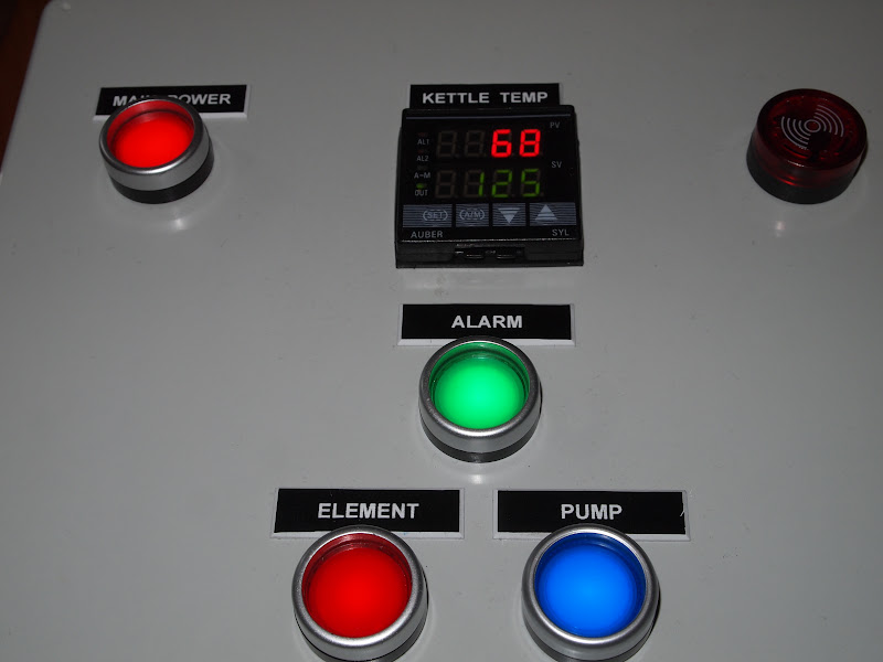
Close up of the front panel with all of the controls lit up.

PC120583.JPG

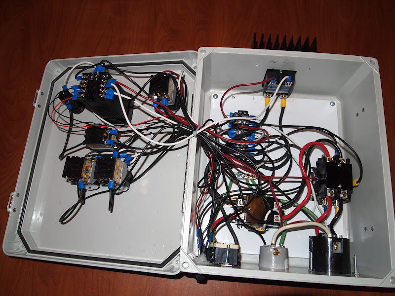
The insides of the control panel. The switches, PID and alarm on the left, the SSR on top, the contractors, terminal strip and outlets on the right.

PC120585.JPG

Attached to the top is the SSR (screwed and thermal pasted to the heatsink). In the top left of the subpanel is a terminal strip, which feeds the hot and neutral lines for the 120V stuff. Below that is the ground bus bar that services all the ground runs. It's hard to tell from the photo, but the paint on the subpanel has been sanded off so the bus bar is in direct contact to it, grounding the subpanel (the only metallic part of the panel.) On the far right is the main power contactor. Just above the 120V and 240V outlets is the element power contactor. Also on the bottom left of the photo against the bottom edge you can see my hack job of securing one of the fuses holders with silicone, because I did not measure properly. (Remember measure twice cut, once....:p)


PC120586.JPG

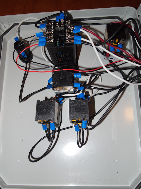
Close up of the backside of the front panel. On the top, from left to right the alarm, PID and main power button. Right below the PID is the alarm button. The bottom row is the pump and element buttons.

PC120592.JPG

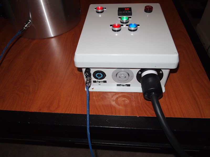
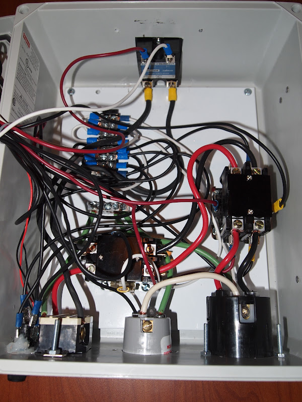
A bottom view showing the power cord coming from the GFCI spa panel (not shown) which is connected to a dryer outlet and the probe going to the kettle RTD sensor.
 
You're right the wiring diagram is incorrect. The black wire from the main contactor should go to the input of the element contactor (and a bus bar), the output from the element contactor should go into the input on the SSR, the output the SSR should go to the element outlet.

One side of the coil should be connected to the element switch, which switches one of the hot legs from the inlet. The other side of the coil should be hooked up the neutral leg of the inlet.
 
Makes sense, that's what your pictures look like, thanks.
For the illum switches it looks like all of them have a jumper from 24 to X2, correct?
 
Not necessarily, you just want to make sure that X1 and X2 complete a circuit (either both hot legs in the case of the main power, or a hot leg and neutral for the pump and element) when the button is closed. There is a good explanation of this in the datasheet for the illuminated button from Auber. Here is a higher res diagram that is easier to read.
wiring-diagram.jpg
 
Gotcha. By the little electrical that I know, I can just jump the neutral between all the switches, alarm and PID instead of going back to terminal block correct? Or does the PID have to be separate?
On second thought can I jump the hot leg as well (#23 on the switches for element and main, #13 for alarm pushbutton and #13 for PID)?
 
You don't have to use a terminal block, you can make the junctions however you like. What you suggest sounds good. As for the alarm button see the diagram I posted in your other thread.
 
Thanks you've been extremely helpful.
It looks like that diagram is still the old way where the ssr is in the wrong spot but I see the changes I ned to make. Thanks again I can't wait to get my first brew in and post some pictures
 
Voltin, it is hard to tell from the pictures but how did you secure your heatsink to the enclosure? I looks like the ssr is screwed to the heatsink but I dont see any screws coming in holding the heatsink to the enclosure
 
Voltin, it is hard to tell from the pictures but how did you secure your heatsink to the enclosure? I looks like the ssr is screwed to the heatsink but I dont see any screws coming in holding the heatsink to the enclosure

The heatsink is screwed to the enclosure via 4 screws which are inset a little bit from the corners of the heatsink. You can see one of them poking out in the top right of the picture containing the SSR.
 
Voltin,

I looked back thru your initial photos and can't tell where you have your temp probe mounted. You mentioned at one point that you didn't recirculate at first, so I'm assuming that you had your probe tip somewhere in side your kettle. If it was near the bottom, did you ever test to see how much temp stratification you had in your kettle?

Thanks,
Keith

The temperature probe is placed approx. 6" above and to the right of the element in the kettle. The stratification is significant, when the element fires you see a rapid rise in the reported temperature that quickly drops if you stir it. I think the best place might be in a Tee at the ball valve bulkhead.
 
voltin - So I have my panel wired, just need to wire up the main panel and the spa panel. Could you possibly post some pictures on this? I know this is simple for most people, but I am confused on a few things.

This is my 30a Breaker I was going to place in my main. It only has two outputs (I am assuming two hots).


This is my 50a breakers that is in the spa panel. It has 3 outputs (two hots and a neutral).


How would I run the 2 hots and a neutral from my main to my spa? Would I just add two wires to one of the two outputs on the 30a? I'd really like to see a close up picture of the inside of your spa panel. I am really brain dead on this part!
 
You were right in what you said, your 30a main panel breaker is 2 hots. You should have a neutral (white) bus bar in your main panel where all the white wires from your whole house connect to. Same with the bare copper ground wire, the probably at connected to the case of your panel.
In the spa panel there should be the same thing, a bus bar for your neutrals and a screw for your grounds. That's why there is a white wire coming from your spa breaker, to should mount to the bus bar in the spa panel along with the one coming from your main panel.

This may help you understand a bit better:
https://www.homebrewtalk.com/f170/spa-panel-wiring-dummies-266751/index4.html#post4437757

Careful when wiring, make sure your main panel is disconnected before doing anything in there.
 
Luke - thanks for the advice. Got it wired and the house hasn't burnt down yet.

Installing the heating element shortly. Is there a general consensus the element be near the temp probe? I saw you mentioned a false reading with it so close to the temp probe. I have a tee in my sight glass for the probe already, so I can mount my element anywhere.

After that I am testing everything! Finally the end is near! That is if I wired everything correctly. *Fingers crossed*
 
Hey guys everything fired up properly and I didn't blow up. Question, how do I reclaibrate my PID? I printed the manual, but it isn't clear on how to. I have the SYL-2352. It is reading way off right now, around 107* F, it is currently in Celcius too. Anyone have a tutorial video? I haven't been able to find a thread similar to what I am looking for.
 
You can set the offset in the menu of the PID it is labeled Pb. If it is way off, you should check your wiring. When my RTD was giving me crazy values when I moved, tightening the screws on the back of the PID solved the problem.
 
I had the water just a hair from boiling and it was still reading back and forth fro 39 to 40. So must be my wiring is wrong somehow. Question, does the controller come in Celcius or Farenheit?

Also, did you happen to install a anode? I forgot that part and got bad rust on the heating element during a leak test. Was looking to do a weldless anode installation.

It comes in Fahrenheit. Did you configure the temperature probe as a RTD in the controller setup? I would recommend looking at the Setup page on Kal's Electric Brewery site (http://www.theelectricbrewery.com/control-panel-setup) His settings are good.
 
voltin - Sitting here thinking while I have my PID auto tuning. Since BIAB is a little different from the traditional brewing, in that we stir our grain bed while it's mashing. Should we be stirring our water while it's programing like we do while brewing to evenly dispense the heat? Or is this not something to be worried about?
 
voltin - Sitting here thinking while I have my PID auto tuning. Since BIAB is a little different from the traditional brewing, in that we stir our grain bed while it's mashing. Should we be stirring our water while it's programing like we do while brewing to evenly dispense the heat? Or is this not something to be worried about?

I would approximate the stirring you would do if you were brewing. Better yet, get a recirculation pump that you run continuously during the mash, and you will be able to keep very precise mash temps.
 
Back
Top