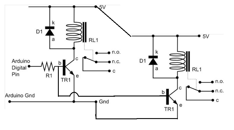
Arduino and two elements

Homebrew Talk - Beer, Wine, Mead, & Cider Brewing Discussion Forum

Help Support Homebrew Talk - Beer, Wine, Mead, & Cider Brewing Discussion Forum:

This site may earn a commission from merchant affiliate links, including eBay, Amazon, and others.

GriFF3n

Member
Joined
Jan 18, 2011
Messages
9
Reaction score
0
Location
Belcamp
I'm looking to do a project with my Arduino to control my HLT. I built a kettle following disintegr8tor's How To and it works great. I'd like to control the two elements with a single arduino and temp probe. I've found how to control one relay with an arduino, but not how to control two . I'd like to control both with a single digital output, but am not sure how to connect the two relays. I'm thinking I can just branch off of the connection between the transistor base and resistor and then mirror what is happening on the other side. Was going to use mechanical relays too. Does this sound right? (Ugly sketch I know:tank:)

sesAT.jpg
 
Yes that will work. Also depending on how much current the coils draw and how much the transistor can dissipate you can wire the coils in parallel and only have one transistor. It depends on the accentual parts used. If you have the part numbers I can look it up.
 
AVRs can output about 20mA. This is enough to drive most small transistors. Lots of people use transistors with AVR microcontrollers; darlingtons are popular because of the high gain.

Is there a reason you want to use 2 relays? If your relay can handle it, why not run both elements off one relay?
 
You have a number of options at hand:

One output, one SSR relay, one or more current draw - easiest

One output, one transistor, one mechanical relay, one or more current draws - second most complex

One output, one (or more) transistors, one (or more) mechanical relays, multiple current draws - next most complex

Two outputs, two SSRs, multiple current draws - rather easy in the grand scheme

Two outputs, two (or more) transistors, two (or more) mechanical relays, multiple current draws - likely a lot of complexity where less would suffice.
 
I second the FET idea. Here is my relay driver I use on a regular basis straight from work. Excuse the interpage connect... basically its a 1k ohm resister to the gate of an Si2318DS N-channel FET that switches ground on the coil of the relay.

I use some pretty expensive Teledyne relays for high reliability applications, but this should work for anything without too ridiculous of a coil current.

relay control fet.jpg
 
AVRs can output about 20mA. This is enough to drive most small transistors. Lots of people use transistors with AVR microcontrollers; darlingtons are popular because of the high gain.

Is there a reason you want to use 2 relays? If your relay can handle it, why not run both elements off one relay?

And this!

DPDT relay will give you two switchable lines to work with.
 
Wow, so many responses! Love this forum!

Here are the relays I intend to use: DIGIKEY.

I will be using two relays because I want the ability to bypass one of them to have on when it is time to actually boil. The Arduino control will be done with a temperature sensor. I will set the temperature to my strike temp and have the elements on until it reaches that temp, then turn off. I will then mash and heat sparge water with a second temperature setting. Once I am done collecting my runnings I will bypass the arduino and have one element fully on.

I will have to research FETS, I've never used them before.

I'll have to draw up my full schematic here so everyone can see what I am trying to do. Thanks again for all the advice fellas!
 
N-channel fets are pretty straight forward, put voltage on the gate and current passes from drain to source with a little voltage drop across the device.
 
N-channel fets are pretty straight forward, put voltage on the gate and current passes from drain to source with a little voltage drop across the device.

As he said, FETs are nice, simple switches. They have the advantage over BJTs of having a high input impedance, so there is very little current draw on the Gate-Source junction.

That relay should work, it is rated for 30A, so make sure you consider that if you ever plan to upgrade to higher rated elements. It doesn't look like there is any diode protection for the coil collapse so be sure to throw some fast switching diodes like a 1N914 reverse biased across the coil do you don't fry your arduino when the coil turns off.

Another option to consider mentioned above are SSRs. They would probably fit your purpose, are pretty cheap, and non-mechanical so you don't have to be as concerns with contact failures.

Lastly when you do your programming, make sure you work in some hysteresis so you don't constantly flip your coils. If this is for your HLT, I'd recommend a 2-3 degree swing either direction from your set point.
 
I don't understand the point of using only one element.

If you are controlling with the Arduino, you should have no reason to switch one element off. Just use both of them all the time.

You should be able to control with both elements from zero to full power. Your circuitry will be simpler.
 
I don't understand the point of using only one element.

If you are controlling with the Arduino, you should have no reason to switch one element off. Just use both of them all the time.

You should be able to control with both elements from zero to full power. Your circuitry will be simpler.

Having both elements on at the same time cause the boil to go out of control. It's fine for heating up quickly, but not when maintaining a boil. Only one element is needed to have a good boil.

gx1400 said:
Another option to consider mentioned above are SSRs. They would probably fit your purpose, are pretty cheap, and non-mechanical so you don't have to be as concerns with contact failures.

SSR's tend to be much more expensive. The mechanical relays I have listed are about $4 each, whereas the solid state relays are about $25.

gx1400 said:
It doesn't look like there is any diode protection for the coil collapse so be sure to throw some fast switching diodes like a 1N914 reverse biased across the coil do you don't fry your arduino when the coil turns off.

Are you saying throw a diode from the Arduino output, or on the relay coil?
 
GriFF3 said:
Are you saying throw a diode from the Arduino output, or on the relay coil?

He's refering to D1 in your original diagram. It would appear that the relays you chose don't have that built in diode. that diode is very important as energy builds up in the coil and when you turn the coil off the energy has to go somewhere. Without the diode it would end up going into your I/O pin and fry it.
 
You need to shunt the relay coil with a diode. There's only one way the diode can go; if you put it the wrong way the current will all go through the diode and the relay won't pull in (and the diode will probably burn out).

It still doesn't make sense to wire your elements seperately. You have a microcontroller and relays, use them! Control your boil electroncially. All you have to do is write the software. I haven't written Arduino in a while but I would do some thing like this for a combined mash/boil controller, with an LM335 temp probe. In boil mode, the dial just adjusts the element duty cycle from 0 to 100%. In mash mode, the dial is a temperature setpoint setting. Totally depends on your temp probe circuit if you can share pots. The pot may be too sensitive in mash mode unless it's multi-turn. No big deal to use 2 pots, anyway.

Code:
//simple combined thermostat/boil control for Arduino. 


void setup(){

int mode = 2;    //read switch on digital pin 2 to detect mode (mash or boil)
int probe = 5;    //temp probe connected to analog pin 5
int elements = 3; //element relays connected to digital pin 3

float deadband = 3;     //amount of temperature hysteresis
float setpoint = 128;    //default setpoint, in raw ADC counts, have to calibrate this
//float setpoint = analogRead(potentiometer)  //or have a convenient temperature setpoint knob
float reading;             //variable to hold the temperature reading 

//do other stuff

}

void loop(){

    if (mode){   //if switch is set to 'mash' mode,  do this 

        float setpoint = analogRead(potentiometer)  //read the setpoint dial
        reading = analogRead(probe);                    //read in the temperature. Will be 0-255. 
    
        if (reading < setpoint - deadband/2){  //it's too cold, turn on the elements
            digitalWrite(elements, HIGH);
        } else if (reading >= setpoint + deadband/2){ //it's too hot, turn off the elements
            digitalWrite(elements, LOW);
        }
    
        delay(1000);  //check once per second

    }


    if ( !mode){    //if in 'boil' mode, do this 

         setpoint = analogRead(potentiometer)  //read the setpoint dial to adjust boil vigorosity
    
        digitalWrite(elements, HIGH);
    
        delay (setpoint *5000 / 255); //stay on 5 seconds if dial is WFO, 0 seconds if it's off 
    
        digitalWrite(elements, LOW); 
    
        delay(255 - (setpoint *5000 / 255) );   //stay low 5 seconds if dial is off, 0 seconds if it's WFO


    }


}
 
I would tie both elements together and use an SSR. I would then implement PWM your firmware to control the duty cycle (throttle) that they are on for. You will probably find that you want more control than just both elements on, both off or only one on. I typically boil at 70-75% duty cycle for 10 gallon batches with a 5500 watt element. When I do 12 gallon batches in my keggle it's nice to knock down by 10-15% when I add hops so I don't boil over. If you are going through all the trouble of setting this up and writing firmware go the extra bit to get better control and you will be glad you did down the road.

Edit: I'm confused by your setup. I was assuming you have 2 elements in the boil kettle.
 
He's refering to D1 in your original diagram. It would appear that the relays you chose don't have that built in diode. that diode is very important as energy builds up in the coil and when you turn the coil off the energy has to go somewhere. Without the diode it would end up going into your I/O pin and fry it.

Ok, thats what I thought. Just wanted to make sure.

crane said:
I would tie both elements together and use an SSR. I would then implement PWM your firmware to control the duty cycle (throttle) that they are on for. You will probably find that you want more control than just both elements on, both off or only one on. I typically boil at 70-75% duty cycle for 10 gallon batches with a 5500 watt element. When I do 12 gallon batches in my keggle it's nice to knock down by 10-15% when I add hops so I don't boil over. If you are going through all the trouble of setting this up and writing firmware go the extra bit to get better control and you will be glad you did down the road.

Edit: I'm confused by your setup. I was assuming you have 2 elements in the boil kettle.

BetterSense said:
It still doesn't make sense to wire your elements seperately. You have a microcontroller and relays, use them! Control your boil electroncially. All you have to do is write the software. I haven't written Arduino in a while but I would do some thing like this for a combined mash/boil controller, with an LM335 temp probe. In boil mode, the dial just adjusts the element duty cycle from 0 to 100%. In mash mode, the dial is a temperature setpoint setting. Totally depends on your temp probe circuit if you can share pots. The pot may be too sensitive in mash mode unless it's multi-turn. No big deal to use 2 pots, anyway.

There are 2 heating elements in the setup. I have not looked into controlling the elements with PWN. I've read some stuff about PID controllers, but wasn't sure I could utilize that with the Arduino. Any links?
 
You need to shunt the relay coil with a diode. There's only one way the diode can go; if you put it the wrong way the current will all go through the diode and the relay won't pull in (and the diode will probably burn out).

It still doesn't make sense to wire your elements seperately. You have a microcontroller and relays, use them! Control your boil electroncially. All you have to do is write the software. I haven't written Arduino in a while but I would do some thing like this for a combined mash/boil controller, with an LM335 temp probe. In boil mode, the dial just adjusts the element duty cycle from 0 to 100%. In mash mode, the dial is a temperature setpoint setting. Totally depends on your temp probe circuit if you can share pots. The pot may be too sensitive in mash mode unless it's multi-turn. No big deal to use 2 pots, anyway.

Code:
//simple combined thermostat/boil control for Arduino. 


void setup(){

int mode = 2;    //read switch on digital pin 2 to detect mode (mash or boil)
int probe = 5;    //temp probe connected to analog pin 5
int elements = 3; //element relays connected to digital pin 3

float deadband = 3;     //amount of temperature hysteresis
float setpoint = 128;    //default setpoint, in raw ADC counts, have to calibrate this
//float setpoint = analogRead(potentiometer)  //or have a convenient temperature setpoint knob
float reading;             //variable to hold the temperature reading 

//do other stuff

}

void loop(){

    if (mode){   //if switch is set to 'mash' mode,  do this 

        float setpoint = analogRead(potentiometer)  //read the setpoint dial
        reading = analogRead(probe);                    //read in the temperature. Will be 0-255. 
    
        if (reading < setpoint - deadband/2){  //it's too cold, turn on the elements
            digitalWrite(elements, HIGH);
        } else if (reading >= setpoint + deadband/2){ //it's too hot, turn off the elements
            digitalWrite(elements, LOW);
        }
    
        delay(1000);  //check once per second

    }


    if ( !mode){    //if in 'boil' mode, do this 

         setpoint = analogRead(potentiometer)  //read the setpoint dial to adjust boil vigorosity
    
        digitalWrite(elements, HIGH);
    
        delay (setpoint *5000 / 255); //stay on 5 seconds if dial is WFO, 0 seconds if it's off 
    
        digitalWrite(elements, LOW); 
    
        delay(255 - (setpoint *5000 / 255) );   //stay low 5 seconds if dial is off, 0 seconds if it's WFO


    }


}

Not quite sure how I feel about this code... but the comments are nice!
 
I have not looked into controlling the elements with PWN. I've read some stuff about PID controllers, but wasn't sure I could utilize that with the Arduino. Any links?

I wasn't talking about using a separate controller. I assumed that since you were going to hook up the elements to an Arduino, you were going to actually use the arduino to control them. Why else would you use an arduino? You can switch relays on with simple pushbutton switches. The point of using an arduino is to program it. You can use PID control if you want, but regular thermostatic control works fine for controlling to a temperature, like for mashing. To control your boil, you can't use temperature control but you can just adjust the duty cycle of the elements.
 
I wasn't talking about using a separate controller. I assumed that since you were going to hook up the elements to an Arduino, you were going to actually use the arduino to control them. Why else would you use an arduino? You can switch relays on with simple pushbutton switches. The point of using an arduino is to program it. You can use PID control if you want, but regular thermostatic control works fine for controlling to a temperature, like for mashing. To control your boil, you can't use temperature control but you can just adjust the duty cycle of the elements.

The arduino will be connected to a temperature probe. The program will monitor the probe and send a control to turn off the elements once the desired temperature is reached. Thats the function of this project. Adding a PID controller is a great idea, I just don't know how to do it.
 
The arduino will be connected to a temperature probe. The program will monitor the probe and send a control to turn off the elements once the desired temperature is reached. Thats the function of this project. Adding a PID controller is a great idea, I just don't know how to do it.

I think I get it, however your using sledge hammer to nail in decking, while it'll get the job done, its the expensive and under-utilized way of doing things.

Just so I have it clear, your using the ardino to set a temperature at which to turn a single relay off while keeping the second heating element on? I believe you'd be much more satisfied with using a PID control set up.

Pulse Width Modulation is a technique where by varying the % you have the heating element on you can control how much heat actually goes into the kettle. PID is a control algorithm used to adjust how much heat to put in based on the Temperature probe.

While you can go out and buy a dedicated PID controller and it may be the easier option in this case, you can program the arduino to act just like that PID controller.
 
There's actually an Arduino library for floating-point PID control. I don't like it and I think it's slow and overkill, but you don't have to write your own PID algorithm, even with the Arduino.

http://arduino.cc/playground/Code/PIDLibrary

Because of the system response times involved, I think that simple thermostat control (like my pseudo-code-example) is sufficient for all brewing purposes.
 
Back
Top