Keep track of your wiring, I am just about to start my wiring and so far this is what I have written down. Please correct and/or add to complete this wiring information.
six post double pole double throw (HOA)
1 - 24v valve (down fire mode)
3 and 4 - 24v (wire specifics??)
6 PID (up/auto)
For lights I would put a 24v light between the HOA (term 6(auto mode)) and the PID and between HOA (term 1) and 24v valve (down fire)
PID SYL-2362
8 (white),9 (red),10 (red) - pt100 temp probe (wire specifics??)
1 and 2 - AC power in (wire specifics??)
13 - positive terminal 6 on HOA switch
14 - 24v valve Neutral
Set points for PID
inty - p100
outy - 4
hy - 3
atou - 0
psb - 0
rd - 0
corf - 0
Manual for syl-2362
http://auberins.com/images/Manual/SYL-2362 instruction 1.6.pdf
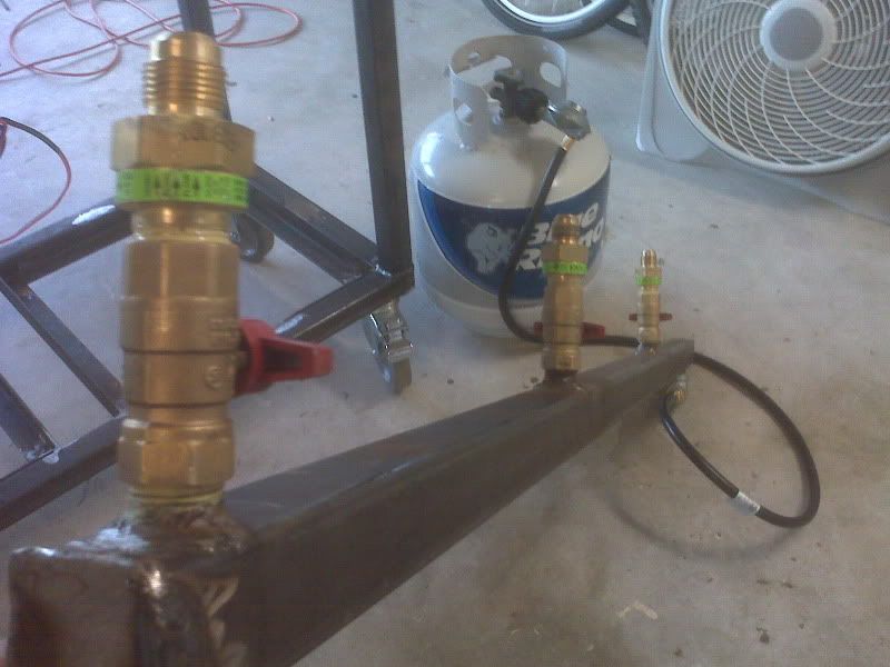
Gas valve (connections at valve)
The "TR" terminal goes to terminal 14 (24v+) and terminal 13 goes to the positive side of the transformer
The "TH" terminal goes to the negative side of the transformer
Switches
Pumps and main power are Single Pole Single Throw
HOA switches are Single Pole Double Throw
Lights
Lights for illumination between PID and valve are 24v
RTD Inputs
White-
Red-
Red-
What wire connects to each post on the radio shack connectors?
24V valve control outputs (on control box)
Power to valves (wire specifics??)
Terminal block (bridge) main power
Minimum 16 pole block (with a layout as displayed below)
1 2 3 4 5 6 7 8
9 10 11 12 13 14 15 16
Functions:
-Power too 24v transformer
-Power too PID
Specific wire information
1
2
3
4
5
6
7
8
9
10
11
12
13
14
15
16
No information yet (to be completed)
Terminal block (bridge) 24v
Minimum 16 pole block (with a layout as displayed below)
1 2 3 4 5 6 7 8
9 10 11 12 13 14 15 16
Functions:
-Power too six post double pole double throw (HOA) which in turn powers the valves
Specific wire information
1
2
3
4
5
6
7
8
9
10
11
12
13
14
15
16
No information yet (to be completed)
Input power module
To main switch (wire specifics?)
Main power switch
to Terminal block main power (wire specifics?)
Pump power switch(s)
power from Terminal block main power
24 volt transformer
power from Terminal block (bridge) main power
power too Terminal block (bridge) 24v
Wire gauge size
10 and 14????
That is all I have at the moment, please add and/or correct this (I will update this post) to make this information as complete as possible. Please check back with this post at a later date for complete information as I will update it as I get more information.
Please note, your specifics may differ. I have taken all information from JLandin and compiled it specific to the build in this thread. Some information comes from word or mouth, manuals, and well informed individuals in an effort to help me optimize my wiring of the system.
Thanks in advance,
Daniel in Frankfurt, Germany

") )
) 


