
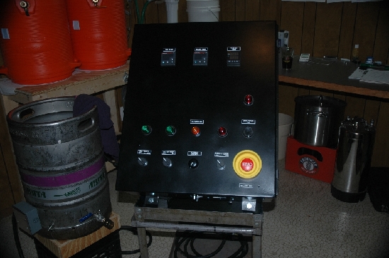
Does anyone see any glaring safety concerns with the following control panel wiring plan?
First let me explain what I am trying to do:
2-Tier 5 gallon all-grain single element electric system
BK = converted sankey keg
MLT/HLT = 10 gallon rubbermaid coolers
5500W element in the kettle
220v Gorman-Rupp magnetic pump
120v stir motor
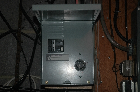
The system will be fed from 30A GFI breaker in the main panel
Process
- Heat strike water in the kettle
- pump to MT while adding grains
- heat sparge water in the kettle (to mash temp)
- recirc through a removable 1/2" tube coil in the kettle
- raise temp to mashout
- pump sparge water to the HLT
- pump sparge water to sparge arm (in MT) while gravity drain to kettle
- boil

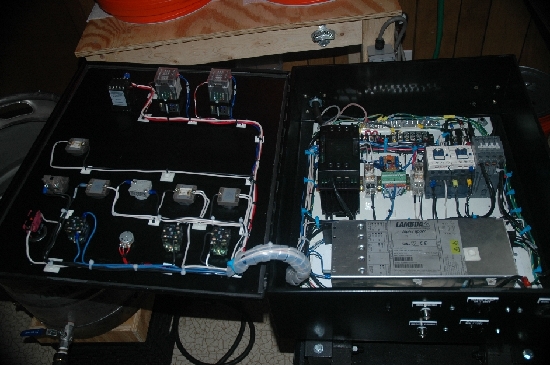
Some of the choices I made were because I already have the watlow PIDs and power controller (gift from a guy in the industrial controls business), 24v power supply, 24v contactor, pump and stir motor. I would like to stay with the 240v 2-conductor line (dryer outlet) if possible, to save cost. However, I wasn't sure if this would work with the GFI - do you have to have a neutral to use the GFI? I mean the pigtail connects to the neutral in the main panel, but do I need to actually have a neutral running to my brew panel too? I was thinking that in a 2-pole setup it monitors the difference between the hots and ground or from hot to hot. Please correct me if I am wrong about this.
I guess one problem I already see is that the stir motor will not be GFI protected (because of the transformer). I could possibly skip this part and run a cord directly to a GFI outlet on the wall. I would appreciate any other thoughts you guys have.
First let me explain what I am trying to do:
2-Tier 5 gallon all-grain single element electric system
BK = converted sankey keg
MLT/HLT = 10 gallon rubbermaid coolers
5500W element in the kettle
220v Gorman-Rupp magnetic pump
120v stir motor
The system will be fed from 30A GFI breaker in the main panel
Process
- Heat strike water in the kettle
- pump to MT while adding grains
- heat sparge water in the kettle (to mash temp)
- recirc through a removable 1/2" tube coil in the kettle
- raise temp to mashout
- pump sparge water to the HLT
- pump sparge water to sparge arm (in MT) while gravity drain to kettle
- boil
Some of the choices I made were because I already have the watlow PIDs and power controller (gift from a guy in the industrial controls business), 24v power supply, 24v contactor, pump and stir motor. I would like to stay with the 240v 2-conductor line (dryer outlet) if possible, to save cost. However, I wasn't sure if this would work with the GFI - do you have to have a neutral to use the GFI? I mean the pigtail connects to the neutral in the main panel, but do I need to actually have a neutral running to my brew panel too? I was thinking that in a 2-pole setup it monitors the difference between the hots and ground or from hot to hot. Please correct me if I am wrong about this.
I guess one problem I already see is that the stir motor will not be GFI protected (because of the transformer). I could possibly skip this part and run a cord directly to a GFI outlet on the wall. I would appreciate any other thoughts you guys have.

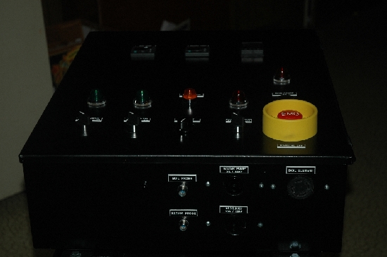
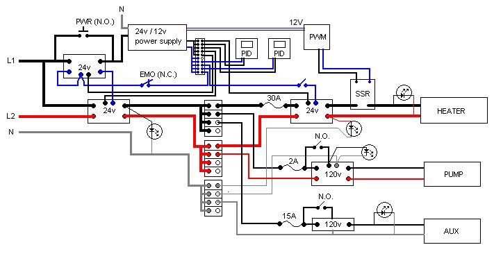
 ) to control the boil because I was trying to get the system done cheaper. Then I came across the free temp controllers, so decided to incorporate them anyway. Eventually I might swap over control to the temp controller. Also, the second temp controller is not in use, but it is wired up. Eventually I will use that to control a recirculation loop for mash temp control.