My brew rig: The Omnibrew

Homebrew Talk - Beer, Wine, Mead, & Cider Brewing Discussion Forum

Help Support Homebrew Talk - Beer, Wine, Mead, & Cider Brewing Discussion Forum:

This site may earn a commission from merchant affiliate links, including eBay, Amazon, and others.

ExHempKnight

Well-Known Member
Joined
Oct 1, 2010
Messages
117
Reaction score
3
Location
Roanoke
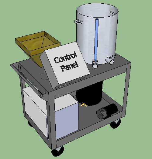
I guess I'm close enough to building this thing, that I can share. It's an amalgamation of several ideas I've gleaned from people, and combined into a do-it-all brewing rig.

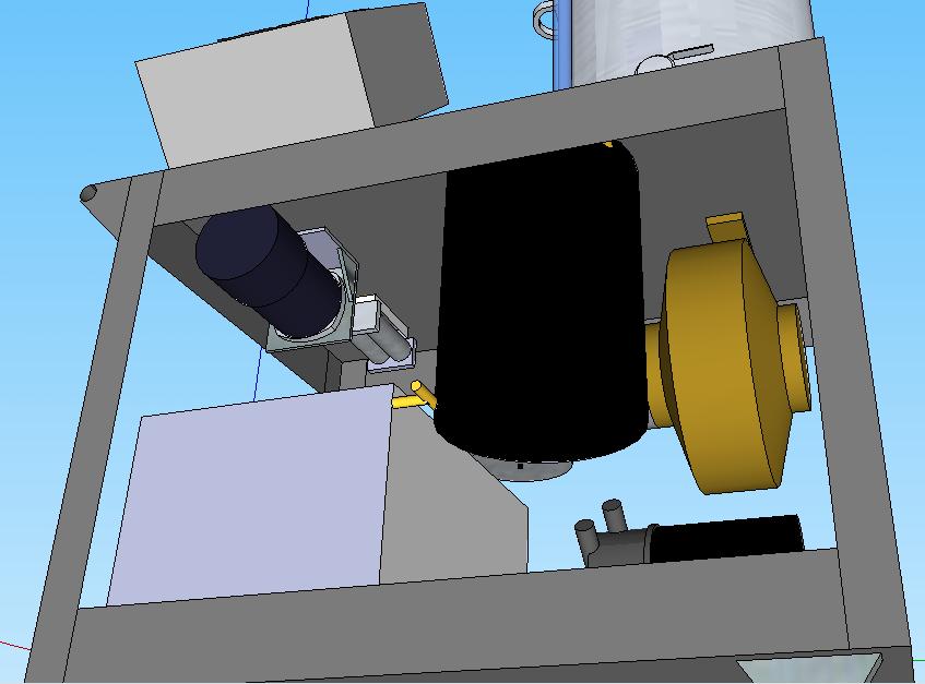
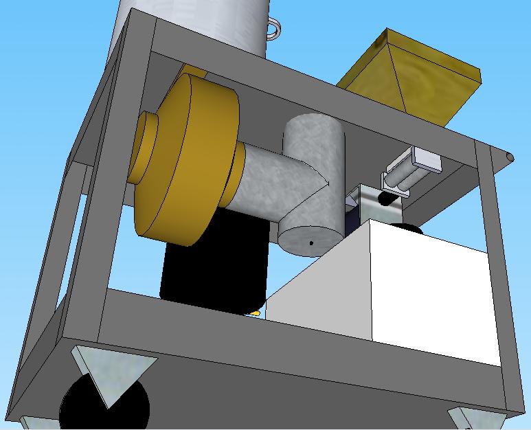
I'll be building it on a cart for portability. It will consist of a motorized grain mill, a single-vessel BIABasket system (a la ScubaSteve), a Bobby_M style CFC, on board water filter, an on-board ventilation system, and a 20-gallon tank with a submersible pump (which will collect the CFC cooling water for later cleaning use).

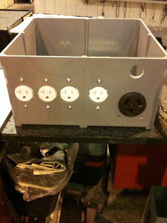
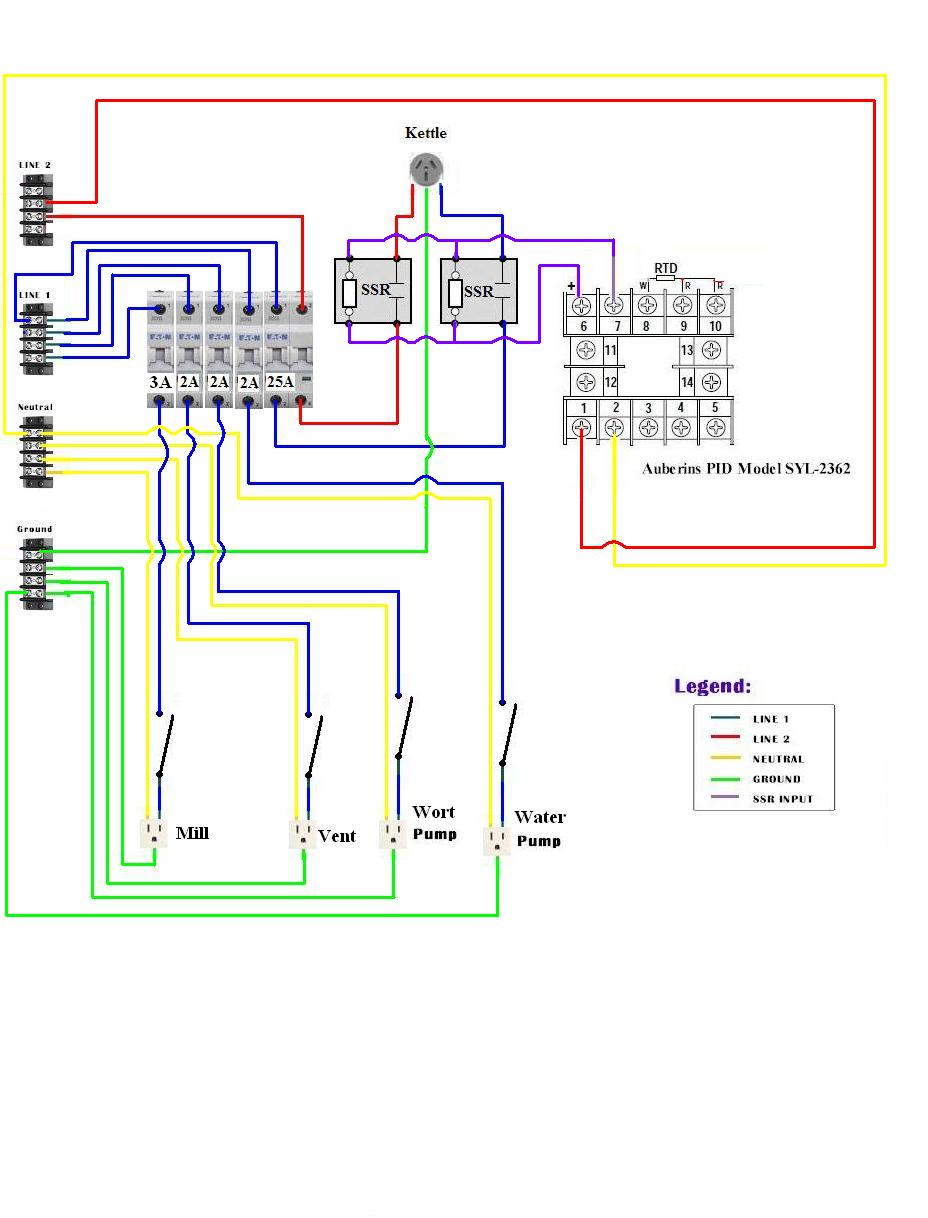
First, the Control Panel schematic (thanks again to P-J for being cool with me stealing and modifying this for my own purposes):
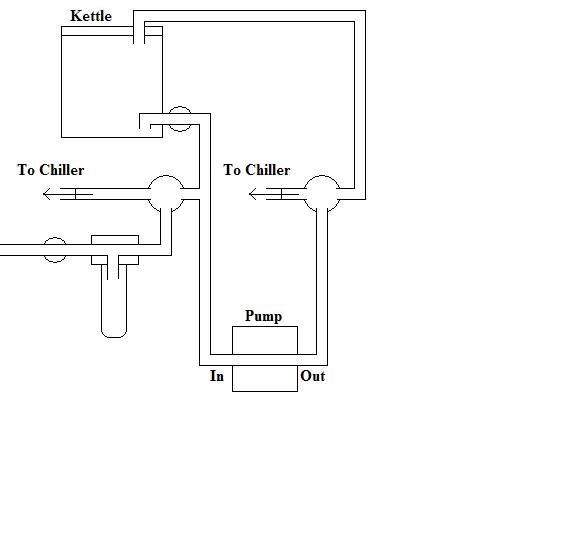
gajtnoqj5j3sknol7h.jpg


Next, the plumbing:
cedepji8ghgrqt7yjxp.jpg


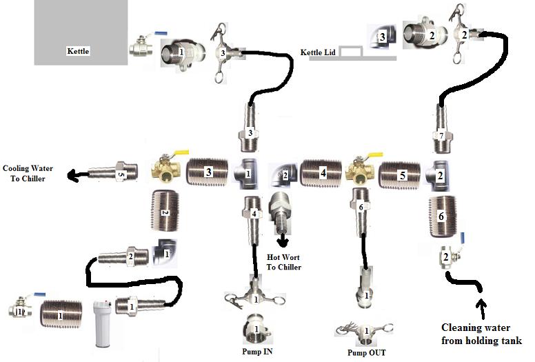
The plumbing again, this time as a parts diagram:
nucgcil4eccvae1uf65g.jpg


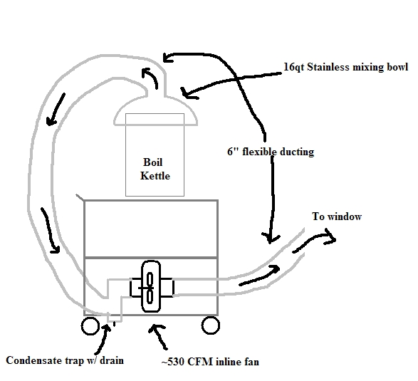
And finally, a crude concept drawing of the vent system:
ze8yc2iqdezoho6uklx.jpg


Constructive criticism is most welcome. Thanks!
 
OP,

Awesome, and thanks for posting a wiring diagram that I can follow to the T for my build, and thanks to P.J. for wiring help in this thread and many others I have read.

You're in Roanoke? So am I. Are you a member of Star City Brewers Guild? I don't make it to many meetings but am "officially" a member.

Can't wait to see the build.
 
Very nice! I can tell you put some work into those diagrams. It looks good...the only thing I might add is to have the ventilation off the rig...or at least QD it somehow. That ducting is going to be a PITA, and clutter your build... so why not hook it up only when you need it?

Also, why not have a bottom drain? That way you don't have to worry about losing siphon or having residual fluid. And it won't get in the way of your basket.

Looking forward to seeing how this turns out! :mug:
 
Nice diagram of the wiring. I have just one question. Why do you have two relays? You only need one per element.
 
The ducting should be relatively out of the way. I plan on using a 6" inline fan like this, which will be mounted to the underside of the top shelf of the cart. I'll use a "T" duct sideways, with one of the branches protruding up through the shelf, the other pointing down with a cap and a drain (condensate collector), and the trunk of the T to the fan inlet.

I plan on using a 25' aluminum dryer hose for the fan outlet. That stuff compresses pretty small, so I figure I'll make a tube out of sheet metal that's maybe 1/2" longer than the compressed hose, and mount it under the shelf as well. This way, when it's not in use, I can just accordion the hose into the tube, and cap it.

That's the next drawing I need to work on... I'll probably have that done tonight.

I don't have a bottom drain because I wanted to be able to set the pot flat, without having to drill holes. I plan on doing CIP like you, but I still want to be able to take the pot off the cart without needing a wrench.

And as for the second SSR... I had originally intended to include a RIMS tube like Scuba, but decided not to at this time. So I figured I wouldn't let the extra SSR go to waste. Plus, it's safer this way. When the PID is off, I know there's no current flowing to the element.

Also, if I decide to add a RIMS tube later, the relay will already be in the box, and all I'll have to do is add another breaker and change some wiring around.
 
You won't be able to accordion the aluminum tube more than a time or two before it starts to fall apart on you. I suggest just using the plastic spiral wound wire reinforced stuff instead and put metal ends on it for a crude QD. Also, I think that 600 cfm will be too much IMHO, but that from the "conservationist" in me. I'm thinking that 300 cfm will be better suited to collect the boiled off water vapor.
 
I know the plastic tube you're talking about... That's where I got the storage idea. That is the ideal solution to my needs, but that **** is ungodly expensive. I don't even know if it comes in 6" diameter, but a google search turned up a 15' length of 10" duct for ~$200.

As for the fan... The 500CFM rating was from an eBay ad, which is probably exaggerated quite a bit. The one I plan on using is ~400CFM, which will probably decrease with ducting installed.

Either way, I'll have it hooked to a 3-speed controller, so I can dial in what I need. Now that I think about it, I guess I should add that to the schematic tonight.
 
Update: Sketchup model! It's fairly basic... I didn't model any of the plumbing. I just wanted to mock everything up to make sure I can fit it all on the cart I plan to use. I think it'll work perfectly. Let me know what you guys (and gals) think. (EDIT... Forgot to put my CFC in the model, so did that)

n5y9eypsfbo89nq954qr.jpg

2sc1l77bkl1re6p2atix.jpg

ojlh3af2veuuvelsg570.jpg
 
Simpler plumbing. And one less valve to buy, I suppose. Those stainless 3-way ball valves are expensive.
 
Are you going to get enough flow for your CFC. I know a lot of people say they need to throttle back their cold water supply or it cools too much. With that high of a flow rate can 1 filter be adequate?
 
I don't foresee a problem.

And if I do find that there isn't enough cooling flow, I'll install a bypass.
 
Do you have really good water there? All the water filters I've seen have been atleast 2 stage?
 
The water is fine... I've made 4 batches with no filtration whatsoever, and they have all tasted fantastic. I figure the filter is just cheap insurance, and will help with consistency.

I plan on using THIS filter housing, with THIS filter.
 
UPDATE: Control Panel finished!

Power outlet side. From left to right: Grain mill, waste pump, wort pump, vent fan, BK element.
ve7zygg3alaycm5btrs.jpg


General component layout:
v4t3wqi6x0hlolntohf.jpg


Heat sinks:
27xvxf3fns5ps19scza.jpg


Colorful spaghetti!
5fi0yypexk6dru20sjrc.jpg


The front panel (bottom switches match outlets, top switch is PID power):
7x2rzrbklpzboaxeuao.jpg


I still need to label everything, and seal the outlets. Also, I plan on putting a small clipboard to hold recipes in that big blank space on the right, and a small kitchen timer above the switches. I was going to put in an indicator light above each switch, but decided it wasn't necessary.
 
Good stuff! I'm pretty much at the same point.....just energized my panel and nothing smoked! So far so good! I'll be interested to see how you organize the spaghetti. I bought some tie-downs, but managing this much 10 AWG can be tricky.
 
Lol that's as organized as it's going to get. It's actually not as bad as the picture makes it look. The DIN rail terminal blocks do a pretty good job of keeping things organized.
 
I don't foresee a problem.

And if I do find that there isn't enough cooling flow, I'll install a bypass.

You can remove the filter from the housing when it comes time to chill. I think that would be a decent solution since you want to drain the water from the filter after each use anyways.

Looking good!
 
What about the mill? How bout a chute that will deposit the grain into a bucket at the side of the rig? That stuff is going to get all over the bottom of the rig. My mill is a separate unit, but I made it so the bucket can press up gainst the bottom of the mill, creating a seal. No dust or other mess, and I just brush the caked on flour into the bucket.
 
My plan is to make a couple of grain bags. Not sure what to make them out of yet... Something tightly-woven enough to not let dust out.

They would have drawstring closures on the top and bottom, and straps to hang from the top. The top drawstring will be pulled tight around the chute exit during milling, then I'll hang the bag above the kettle by the straps until the water reaches strike temp. Then I'll open the bottom drawstring and let the grain fall into the kettle.
 
UPDATE!

I finally got around to doing some more work on my rig.

First, a mockup of the general component layout:
198916_1955159957983_1212233519_32395383_7678529_n.jpg


Based on various ideas gleaned from other HBT-ers, I came up with a rather simple method to support my mash basket to allow the spent grains to drain:
265007_2200837379765_1212233519_32701188_5940279_n.jpg


This is the support in the stowed position:
253405_2200833659672_1212233519_32701180_5590820_n.jpg


Finally, a closeup of the support arm. I'll also use this to support my "vent hood" during the boil.
264919_2200838339789_1212233519_32701190_173404_n.jpg


Left to do:
-Final routing/mounting of plumbing
-Routing ventilation ducts
-Mounting control panel
-Mounting grain mill
-Constructing/mounting mill hopper

Making progress!
 
Back
Top