More illuminated switch questions

Homebrew Talk - Beer, Wine, Mead, & Cider Brewing Discussion Forum

Help Support Homebrew Talk - Beer, Wine, Mead, & Cider Brewing Discussion Forum:

This site may earn a commission from merchant affiliate links, including eBay, Amazon, and others.

erik

Well-Known Member
Joined
Apr 15, 2010
Messages
48
Reaction score
2
Location
San Jose
I bought these guys and think that I got the wrong thing, based on the below description.

P1,2 : Switch 1a, SPST
P3,4 : Led lamp P3=+,P4= - (no resistor inside)

It looks like I need to put hot on wire 3 and common on 4, but I'm guessing that I'll burn out the LED if I use 110V.

Can anyone push me in the right direction?
 
Looks to me like you need to provide a low voltage DC source and a current limiting resistor for the light in the switch.

edit: the fact that the P3 and P4 are described as "+" and "-" means that it wants DC and not AC.
 
typically you're in the range of 20mA at about 2v for most LED's. If you have some low voltage DC available (12, or 6V from a small phone charger or whatever) then connect the + to + and - to - with a resistor that will limit current to 20mA.

example)

with a 12Vdc supply

R = V/I
R = (12V - 2V)/20mA = 500 ohm resistor

Power = i^2 x R
P = 20mA^2 x 500
P = 200mW so use a 1/2W resistor (>2x margin of safety)
 
Thanks! It looks like I'll try to use the idea posted in the LED-tipped toggle switch thread.


switch.jpg


Of course I found that after submitting this thread :eek:
 
a better idea than having the 1n4004 in series with everything is to have it in reverse parallel with the LED. That way there is no way of hurting the LED. The way you have it, the LED still has to handle a reverse voltage of up to (or more) half the AC voltage. With it in reverse parallel then the LED only sees .7V max.
 
a better idea than having the 1n4004 in series with everything is to have it in reverse parallel with the LED. That way there is no way of hurting the LED. The way you have it, the LED still has to handle a reverse voltage of up to (or more) half the AC voltage. With it in reverse parallel then the LED only sees .7V max.

I'm not sure I understand your description. Can you post a schematic (even a quick scribble)?
 
I like Bjornbrewer's suggestion. I drew up a small schematic to make it clear, but have no idea how to post an image (probably not on good enough standing anyway). wither way, try to imagine the diode and led wired in a loop, with the triangles pointed clockwise (so if the led wer on the left, and diode on the right, the LED trianglw would point up, the diode triangle would point down). then, at the junstions where they meet, thats where you connect your HOT on one side (top), and then your resistor to ground on the other (bottom). make sense?
 
google images is my friend.... check this out:
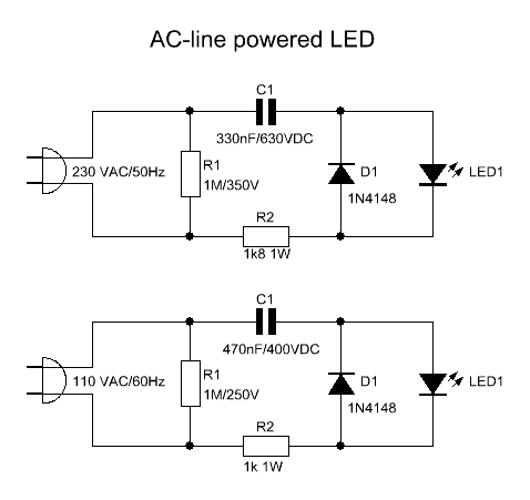
acled.gif

Dont worry about R1 and C1 in those pictures, they're a little over kill. just keep your resistor (R2 in these pictures) high enough. the 3.6 kOhm that Bjorn suggested is probably perfect. the idea is that when current goes one way, it passs through the LED only. when reverse, it passes through the diode. since it passes (and its shorted through), there is negligible reverse voltage build up. if you just put them in series, the revers voltage stays, and all you've done is cut it in half, and since most LEDs break down at low reverse voltages, it wont cut it.

Are you saying we don't need R1 and C1, or are you saying the values are too high on those? If too high, what do you recommend for R1 and C1?
 
you don't need them. They are actually quite pointless and only add components and complexity for no reason. You just need the diode and one series resistor (R2 in that schematic).

The capacitor is there to limit the diode/LED current...it acts as a resistor of sorts. R1...i think that's there for stability only (dampen oscillations) and R2's only job is to reduce charging current of the capacitor. If you take out the capacitor there is no need for the dampening resistor and then R2's function will be to limit the diode/LED current. The advantage of this circuit with the capacitor is that you don't need a big 5W resistor to limit the diode/LED current. So if size is a problem, this may be a better circuit, but I don't think that's an issue.
 
You guys rock! Thank you!

I have ordered diodes and resisters (ebay) and will build this as soon as they show up.
 
Excuse my ignorance here ...

For the following LED Multi colors, it shows the forward voltage as ~ 3.1V for most LEDs, and then ~ 2.1 for the red and yellow LEDs. For the 2.1V LEDs, will I need a different Diode/Resistor combination?

Thanks!
 
ignorance excused! :D

The diode will stay the same, but the resistor may change. Use the formula I used on the first page except the source voltage will be 120V (instead of 12 or 6)

Example)

Vled = 2.1V
R = (120-2.1)/20mA = 5895 ohms

Vled = 3.1V
R = 5845 ohms

practically you should use a 5.9kOhm resistor (or close) and you'd be good with any of those LED's.

You should know the forward current of the LED as well, but 20mA is a typical value.
 
Bjorn,

Awesome, thanks a lot. This makes perfect sense now. Have to remember all my college electronics equations :)

Thanks again!:mug:
 
Bjorn pointed this out, but it may have gotten lost...
The advantage of this circuit with the capacitor is that you don't need a big 5W resistor to limit the diode/LED current
sice we're keeping the circuit simple, we need it. most commonly, resistors are 1/4 watt, meaning they can dissipate .25 watts of current without blowing up. in this case we're dealing with about 2.5 watts:
power (watts) = current x volts
20ma x (110 volts - 2.1v across led) = .02 x 107.9 ~= 2.2watts
so, while the 5 watts maybe a little high, its safe. id get 2.5 watt resistor minimum.

with how ratings of resistors are so skewed and most are rated with a 50% duty cycle or some ungodly high temperature rise, it is good practice to double the power capability of the resistor. I think I mentioned this on the first page. If you calculate 2.2W, use a 5W or greater.

most resistors will NOT handle the power that they are rated for...don't ask me why, it's just a BS ratings game. I deal with it all the time at work.
 
Are you saying we don't need R1 and C1, or are you saying the values are too high on those? If too high, what do you recommend for R1 and C1?

Does anybody still care about this? Here's my input on this whole thing.

C1 is doing the heavy lifting in this circuit. The power dissipation (heat) of the original circuit is mostly eliminated by using the reactance of C1 (no power dissipation), which is the point of using C1. The circuit without the cap will get hot, while this one wont. For the 110V circuit example, C1 sets the LED current to 19mA or so, but only for half a cycle. On the average the LED will glow as if it had about 9.4mA through it constantly. Bigger capacitor, more current.

The purpose of R2 is to limit inrush current should you be unfortunate enough to plug in the thing when the voltage is at its peak, about 156V for the 110V AC circuit. That could destroy the LED or the diode. The 1K resistor limits the peak inrush current to 156mA, which dissipates quickly as the capacitor is charged. During normal use R2 dissipates about 0.36W, so 1/2W might work but 1W rating is a safer choice.

The purpose of R1 is to discharge the capacitor after you unplug the circuit so that you will not get a shock from it. It has negligible power dissipation. Eliminate at your own risk.

I used the 110V example of the schematic to calculate values. They will be a little higher using a 120V supply (9%).

Is that more information than you wanted? :)
 
I guess my short explaination wasn't good enough? ;)

you're right about the R1 discharging the cap...good call. Still all overkill though for such a simple application.

Oh it was good enough all right. I just felt like the benefit (less heat) of the more complicated circuit got lost in the discussion. In fact, using modern high-efficiency LEDs I would drop the cap to 220nF and R2 to 560 Ohm 1/4W. There would be no noticable heat at all in that circuit. Still, overkill, you are right.

Bjorn, we seem to have a few things in common: name(?) , EE, good beer. Good talking to you, sir.:mug:
Bjorn J.

likewise!

you're first name is Bjorn? My last name begins with Bjorn...with a lot of letters after it :D

Cheers,
Paul
:mug:
 
Hey,

Just found this post... sorry to revive a dead post. But I was curious how the values for C1 and R1 were calculated? Thanks.

-Eric
 
Hey,

Just found this post... sorry to revive a dead post. But I was curious how the values for C1 and R1 were calculated? Thanks.

First C1.
We decide what the average LED current should be, say I = 10mA RMS. Since the LED only lights up during one of the two half-cycles, we need to double the current during that half-period to arrive at the average current overall.
Compute circuit impedance z = (110V - 2V) / 2I . I have assumed a 2V drop accross the LED. Modify as needed.
This means that the capacitor's reactance is then xc = SQRT( z^2 - R2^2 ).
Finally we find C1 = 1 / (2 Pi f xc) = 499 nF when R2 = 1KOhm and f = 60 Hz.
The closest standard value is 470nF.

Now R1.
We just pick the largest commonly available value, 1MOhm, and see what the time constant of the voltage decay is.
Tau = R1 C1 = 0.47 sec. The capacitor will lose 63% of its charge every 0.47 sec. That sounds about right so we stop here. If Tau were several seconds we'd reduce R1.
 
Ah. That makes sense. It has been a while since I have done that math. To me this makes a lot more sense than the purely resistor based as well. The pure resistor based would dissipate a ton of energy versus the capacitor based. I do have a question though... is there any benefit to using the RC based instead of a transformer and a full wave rectifier? Other than simplicity and cost?...
 
Ah. That makes sense. It has been a while since I have done that math. To me this makes a lot more sense than the purely resistor based as well. The pure resistor based would dissipate a ton of energy versus the capacitor based. I do have a question though... is there any benefit to using the RC based instead of a transformer and a full wave rectifier? Other than simplicity and cost?...

you still have to limit the current through the LED so you would still need some impedance in the circuit (ie resistor, capacitor, etc.) you're not gaining anything with a bridge and transformer except lots of cost and bulk.
 
Ah. That makes sense. It has been a while since I have done that math. To me this makes a lot more sense than the purely resistor based as well. The pure resistor based would dissipate a ton of energy versus the capacitor based. I do have a question though... is there any benefit to using the RC based instead of a transformer and a full wave rectifier? Other than simplicity and cost?...

Simplicity and cost is it.
For a variable load a transformer is much better because the RC is strongly dependent on the load current.
A transformer is also safer because the low voltage circuit is not directly connected to the line power. If we open the circuit at the load, both the RC and R circuits deliver line voltage whereas the transformer doesn't.
 
Thanks. Last question then... why is the value of R2 1K. It would seem that if we have the V across the resistor to be 108V (110V - 2V for the LED) and the current is limited to .02A then the resistor should be around 5K or am I missing something?
 
Thanks. Last question then... why is the value of R2 1K. It would seem that if we have the V across the resistor to be 108V (110V - 2V for the LED) and the current is limited to .02A then the resistor should be around 5K or am I missing something?

During normal operation most of the voltage is accross the capacitor and some smaller amount across R2. The voltages will be 90 degrees out of phase and may add up to more than the supply voltage.

The purpose of R2 is to limit inrush currents. Suppose we plug in the circuit when the 110V AC waveform is at its peak. This instantaneous step of 156V goes right through the capacitor as if it were a short. Take off 2V for the LED and we are left with 154V accross R2. If R2 is 1KOhm it limits this inrush current pulse to 154mA. This should be in the safe region for the LED and the diode D1. This pulse is short, less than 1ms, so there is no concern of burning up the resistor.

So how much power is dissipated in R2 during normal use? If we calculate the current with the chosen component values we get 18.8mA RMS (the resistor is heated in both half-cycles). The power dissipated in R2 is i^2 R = 0.355W. A 0.5W resistor is perhaps pushing it so 1W is a safer choice. We can see from the square relationship between current and dissipated power that if we lower the current by half the disspiated power drops to 1/4. Suppose we design the circuit for 4mA LED current (8mA R2 current), R2 dissipates 0.064W. A 0.25W resistor would be plenty adequate.
 
Back
Top