phreaky
Well-Known Member
Ive been wanting to get some more consistency in my brewing for a while now, and also wanted to simplify the brewing day a little bit. Like everyone, Ive had plans for a stand floating around in the back of my head, but one thing I wanted to keep about my current system is the ease of portability. Keeping that in mind, I changed my plans a bit, and decided to start rethinking the system. My primary concerns were:
Portable
Consistent
Ability to run on 240, 120, or propane, depending on where Im brewing
Compact
Sparge water on demand, no more HLT
Switchable between high and low power for strike/sparge and mashing.
Now some of these wont be able to be met at all times, but having the ability go from brewing at home with 240 power, no HLT, and constant mash temp from the RIMS tube, to going to a buddys house, and plugging in to 120 and heating with propane is worth the trade off to me.
The system isnt totally done yet. Ive still got to put an electric element in the boil kettle, and build a nicer stand to set the Mash and Boil on, but its close enough Im ready to share. So enough of the babbling, how about some pics? Warning, there will be a bunch.
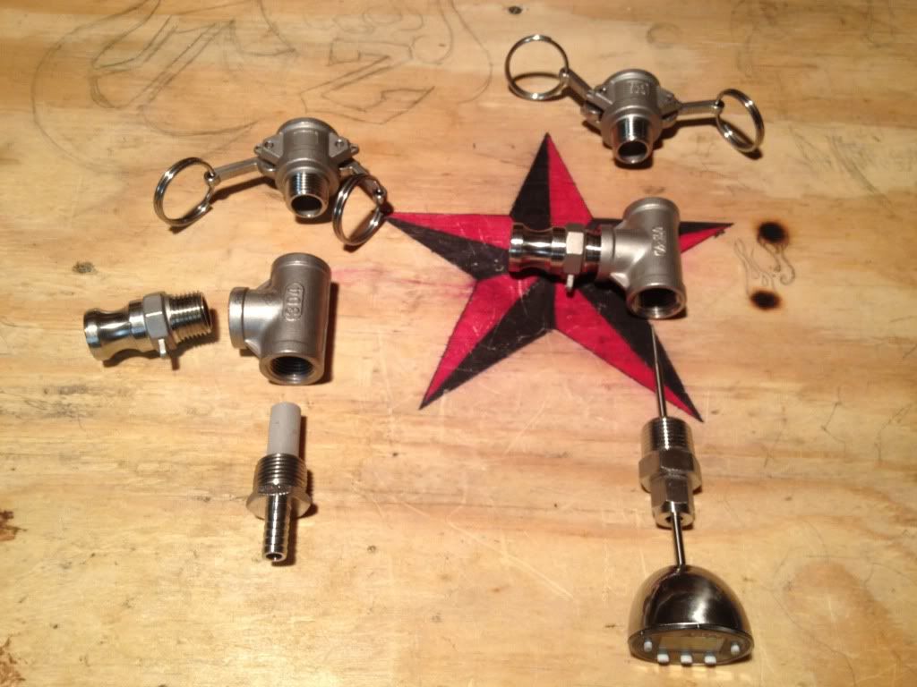
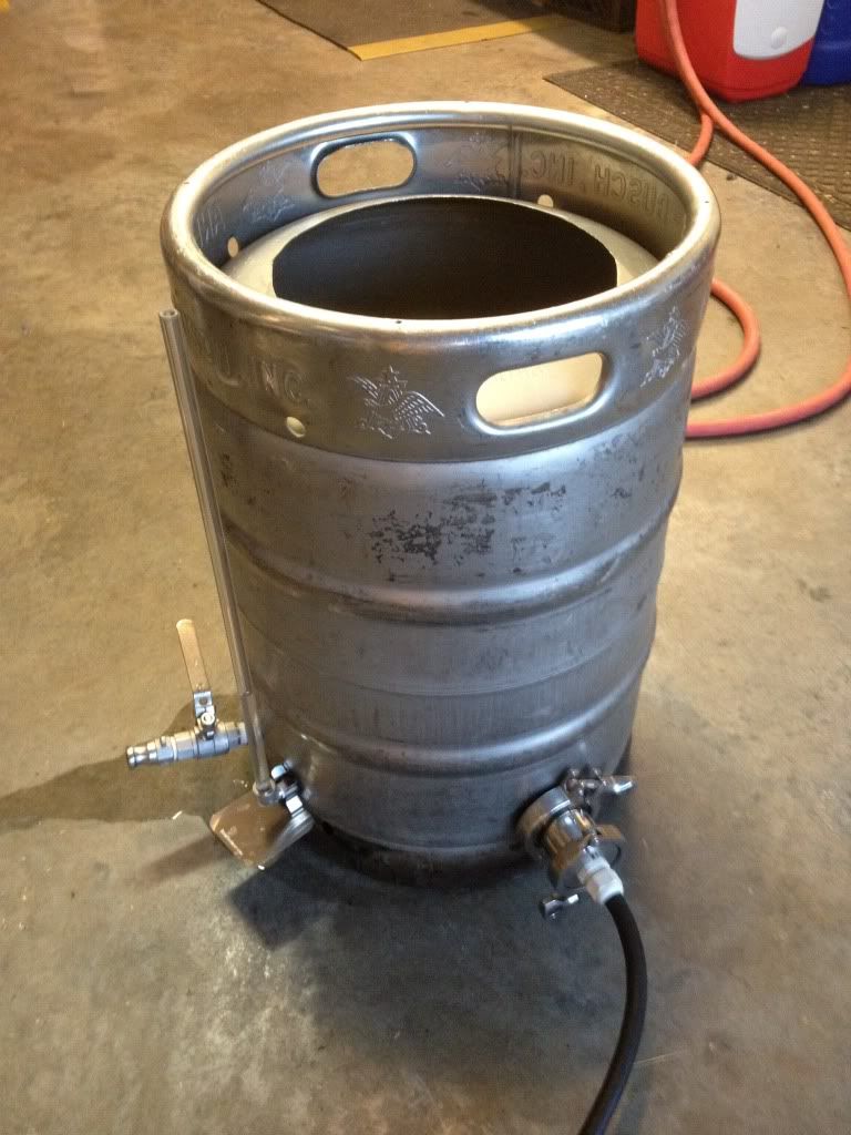
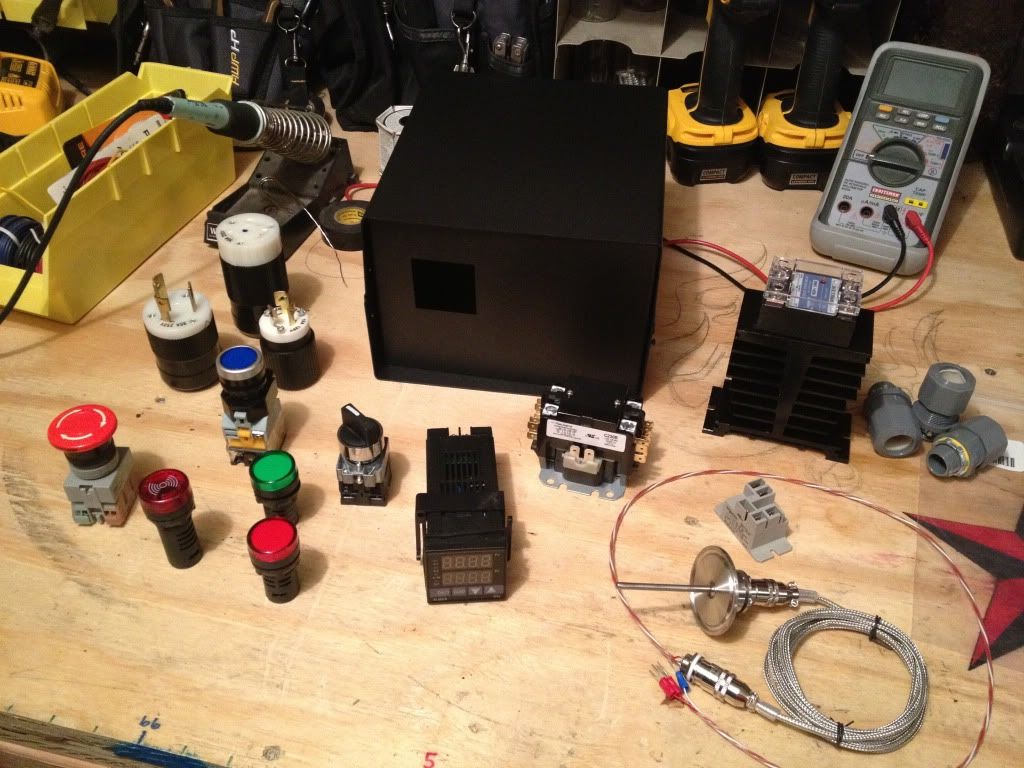
First, I started with a bunch of parts.
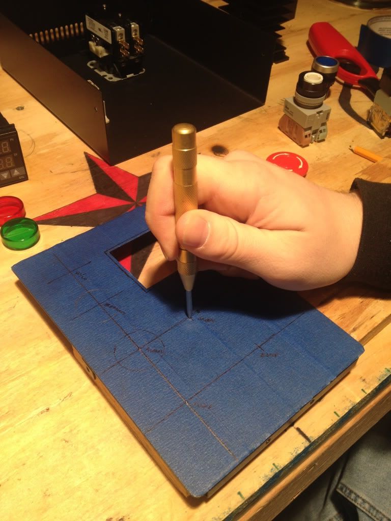
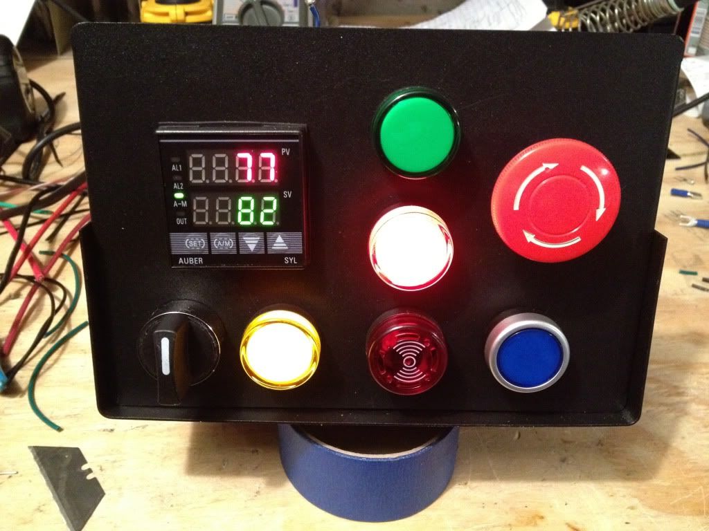
Next came the layout. I started by covering the Auber project box with masking tape and laying out the parts.
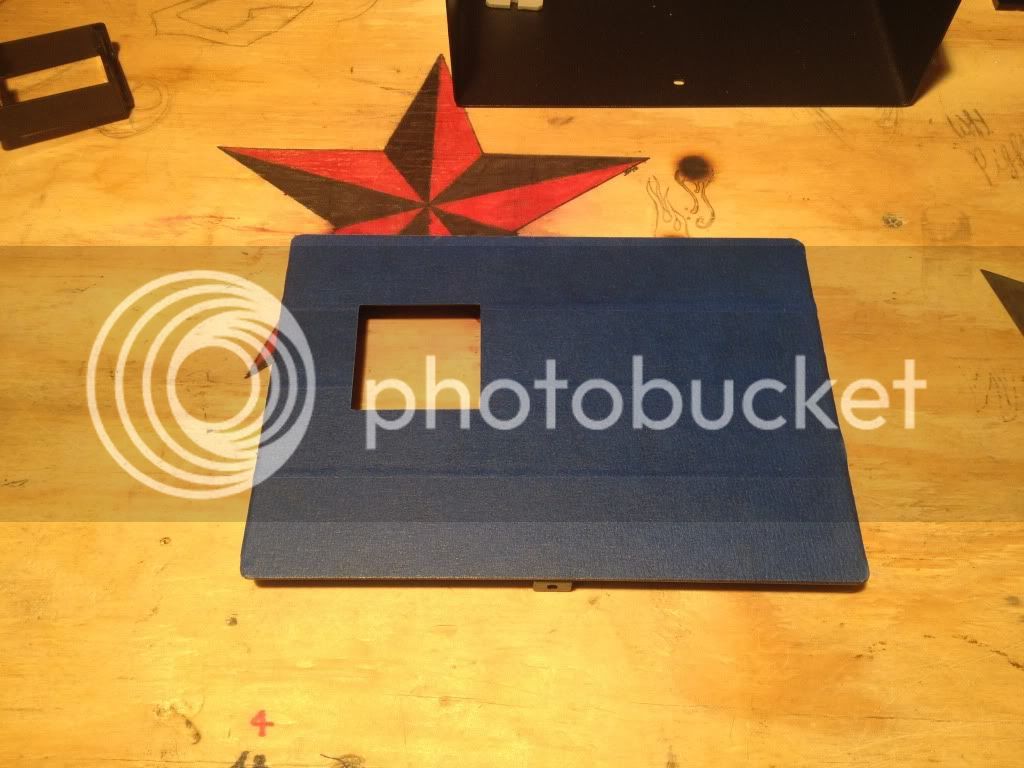
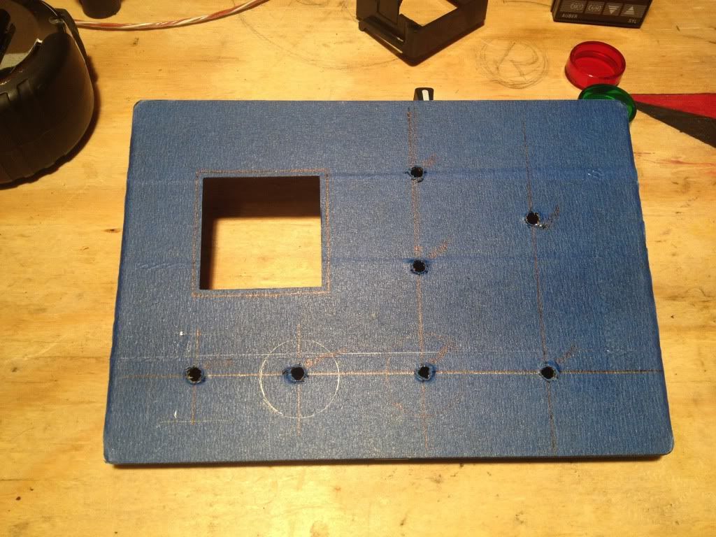
Following that, I center punched and pilot drilled the locations, then followed up with a unibit.
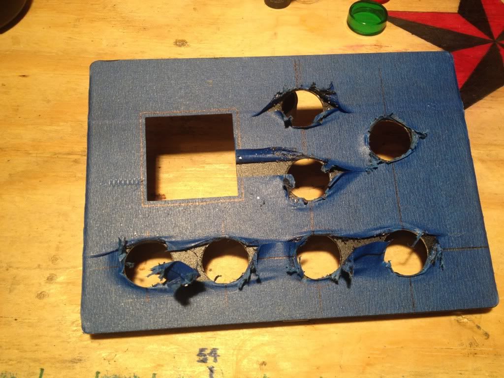
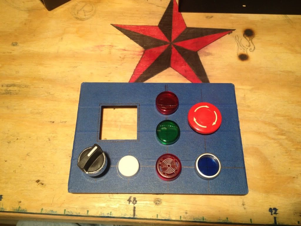
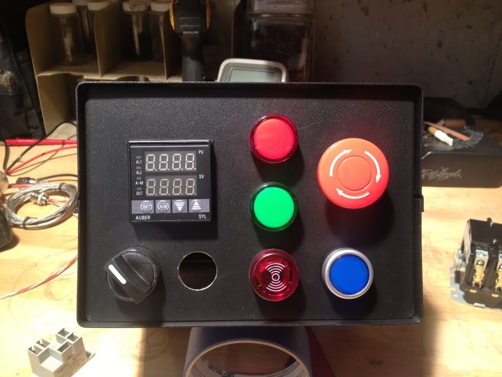
After removing the tape and filing the edges, it was time for a test fit. Due to a screwup on my part, I forgot one light from the order and had to place a second one.
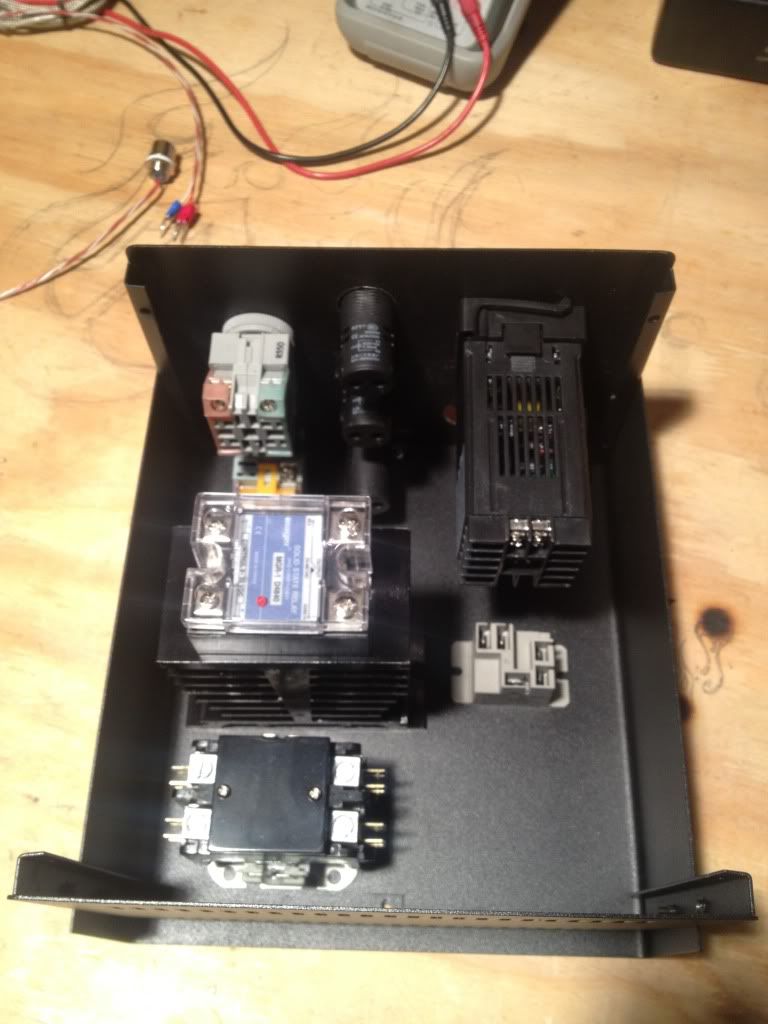
Next came time to design the inside layout. Looking at all of my parts, I was definitely worried about space. I also forgot one relay, so ended up waiting on that too.
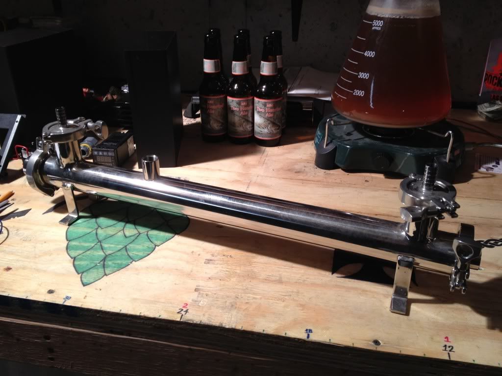
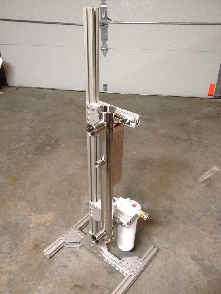
While waiting for the forgotten parts to show up, The RIMS tube from Stout Tanks showed up. This thing is a beast!
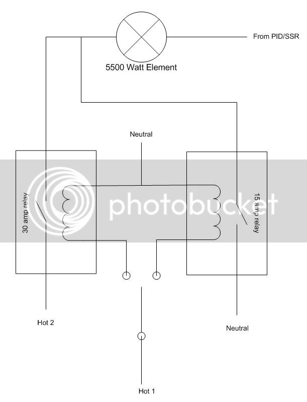
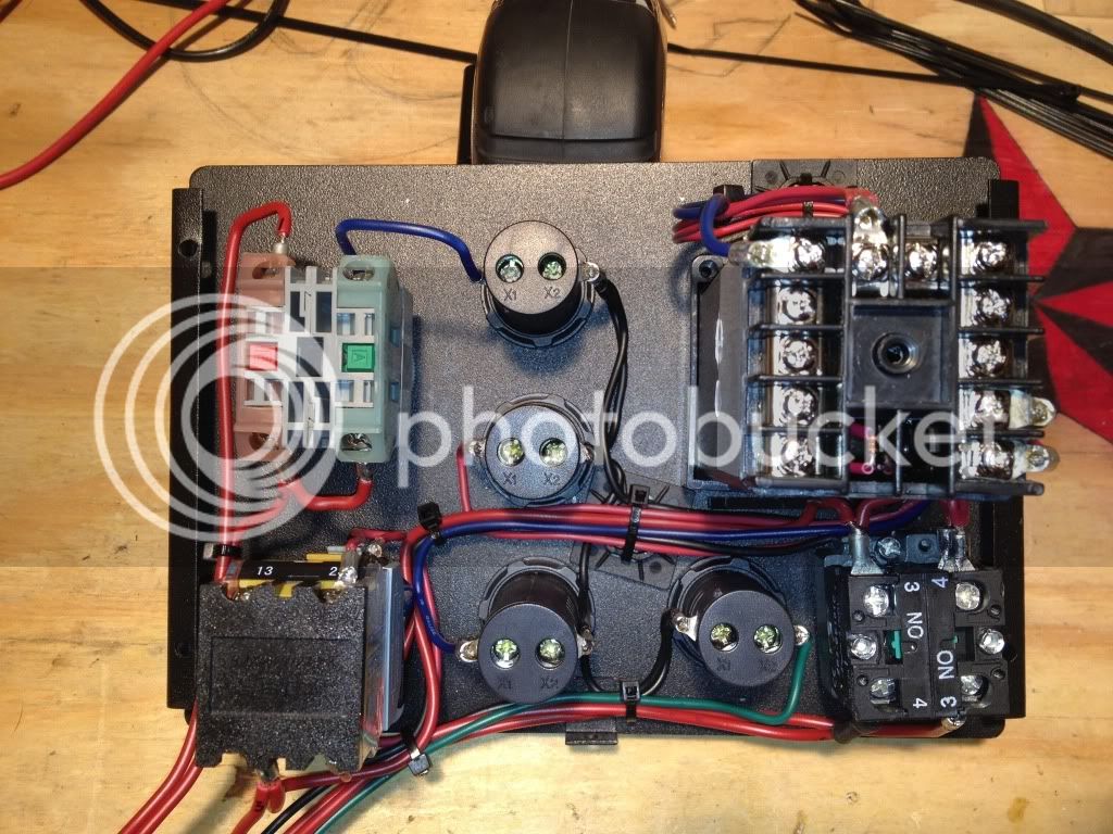
Time to start wiring. First rule, make a plan, schematics help. Then, to make it easier on yourself, make an actual wiring diagram that looks like your layout. Run through it a couple times in your head. Trace the paths down, keep that magic smoke inside the devices, not out.
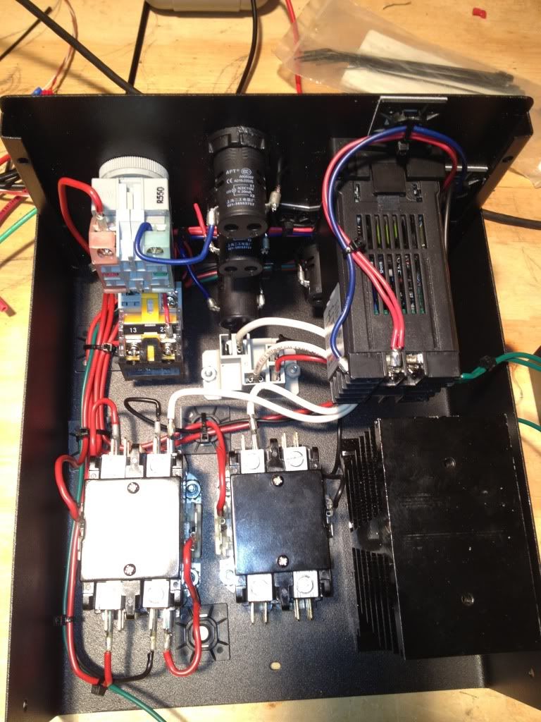
Its alive! Time to cobble stuff together for a test.
First test didnt go so great, lots of leaks from the PTFE gaskets. I ended up ordering new silicone gaskets, but after a good thorough cleaning, the PTFE gaskets worked the next time. While waiting on the gaskets to show up, my brewing buddy dropped by with the next major parts.
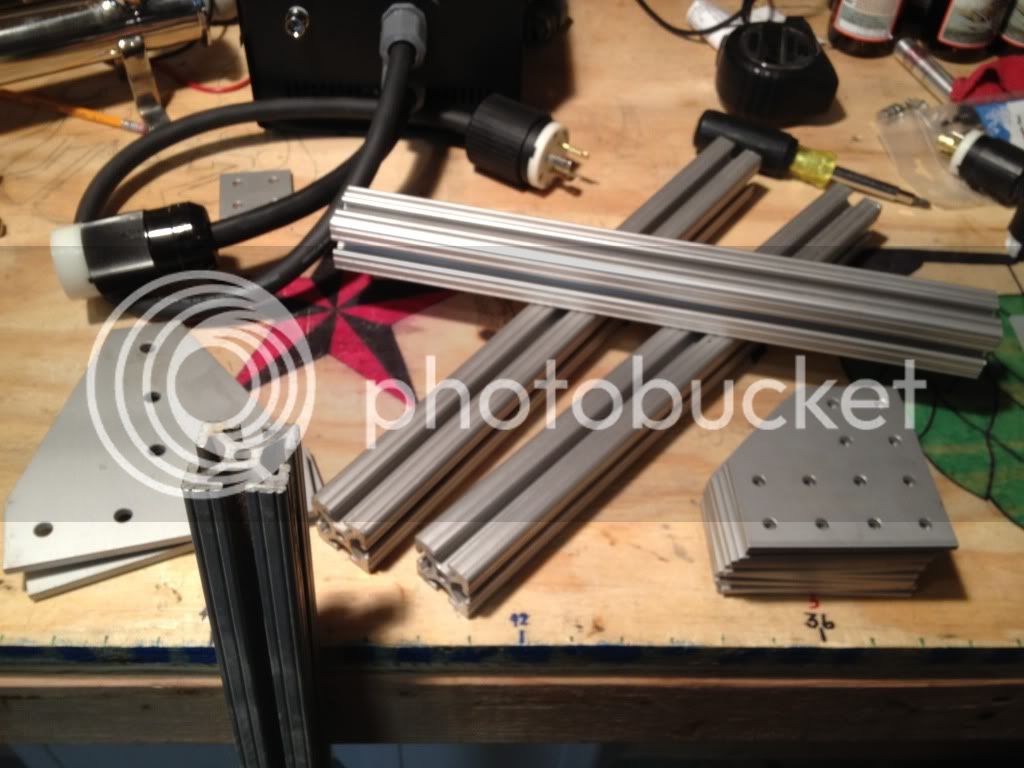
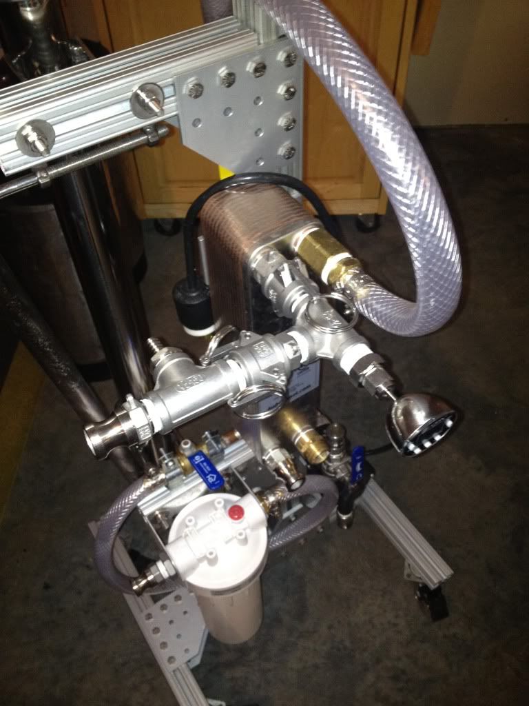
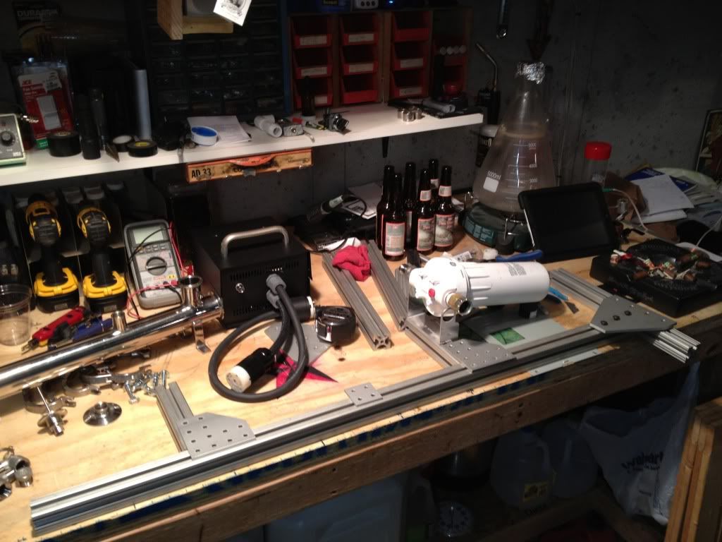
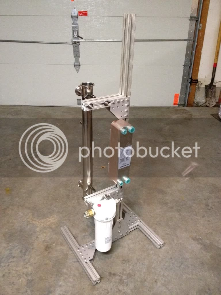
A couple of nights of sketching, and playing around eventually lead to this. I also picked up a new DudaDiesel B23-30 chiller.
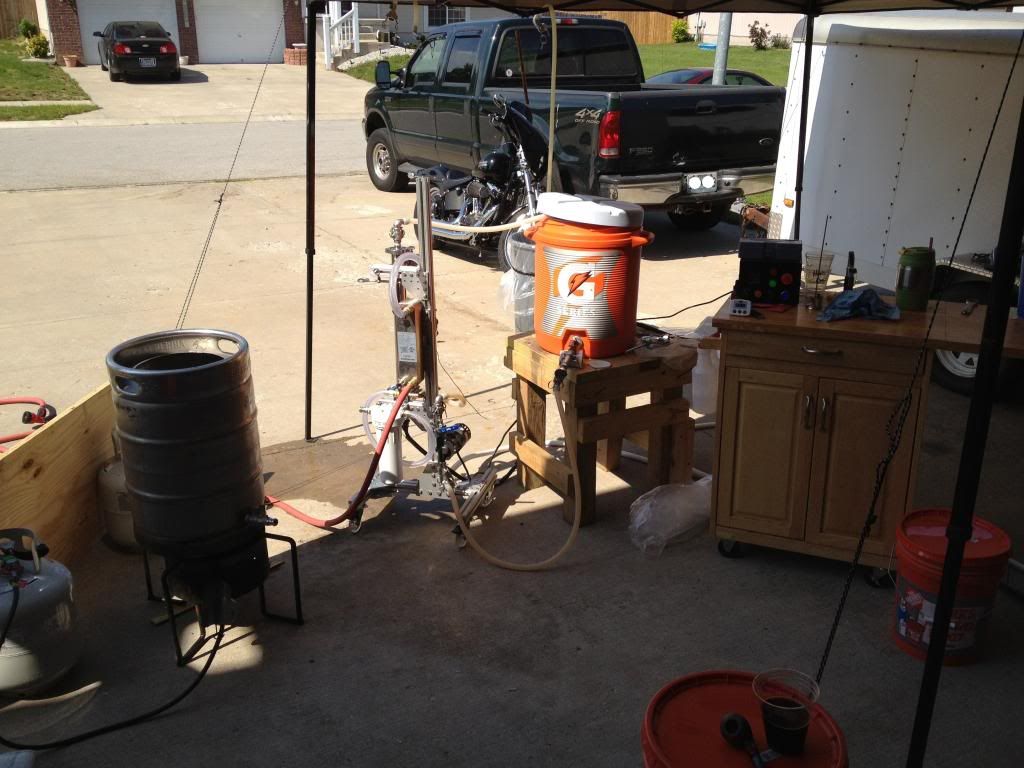
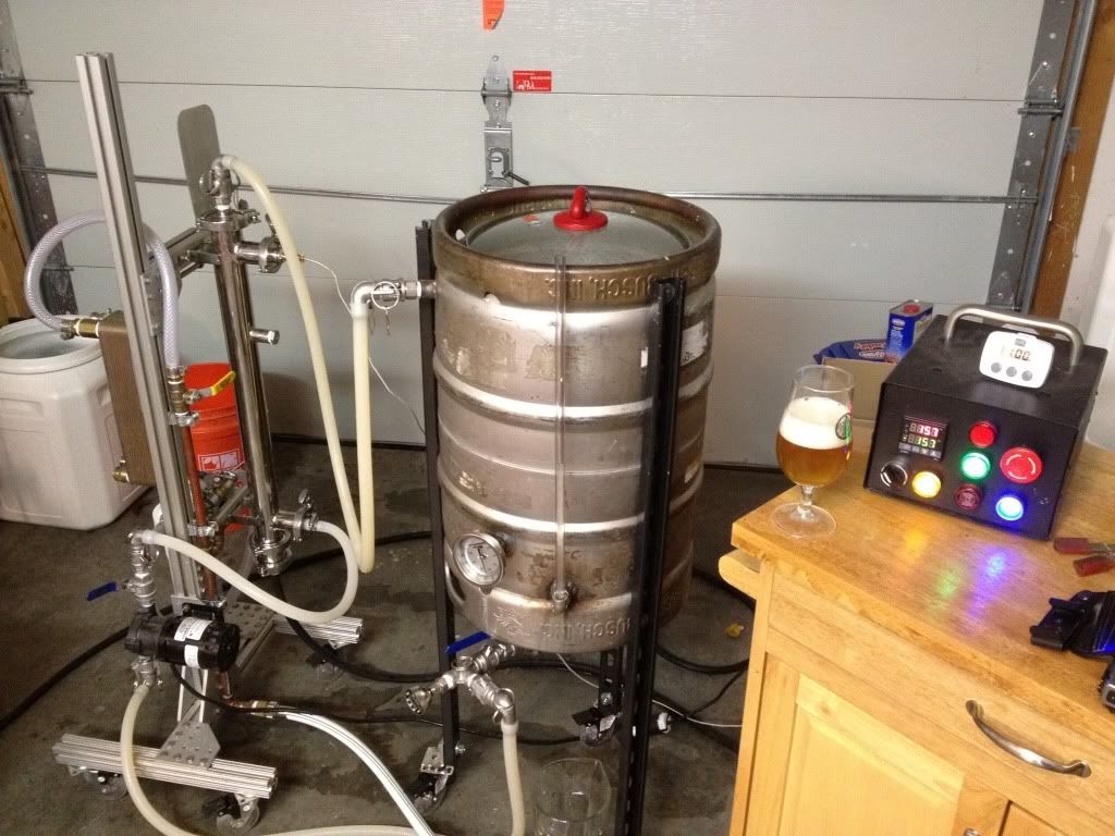
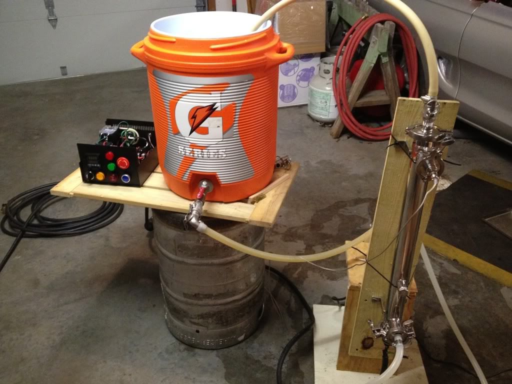
Now its time for a good test and cleaning.
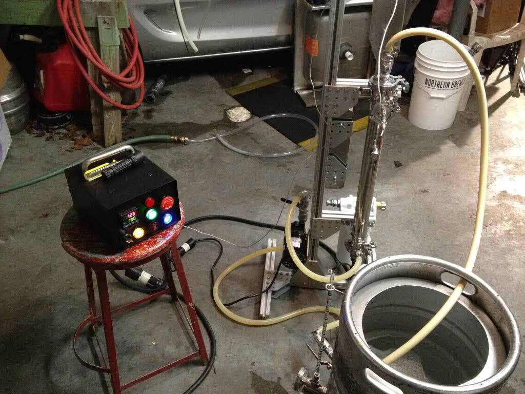
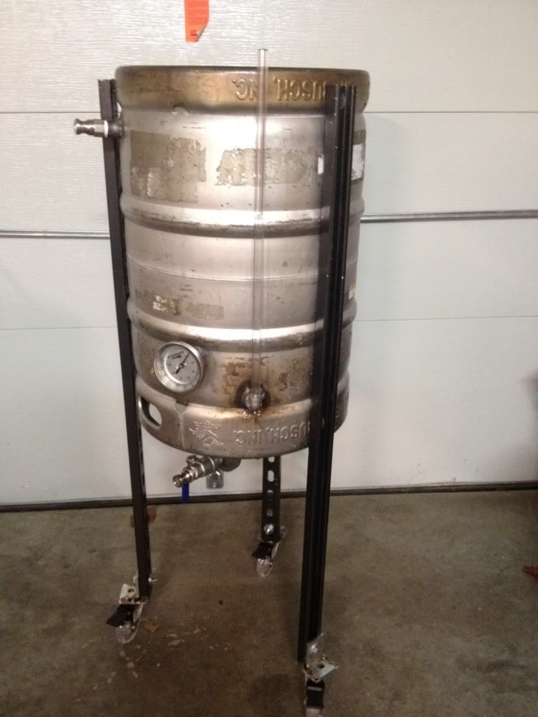
At the time of this test, I didnt have my 240 outlet installed yet, so I was only able to run it on 120. Running on 120, it was able to hold the temps well, all while being plugged into a 15 amp GFCI outlet. Since then, Ive gotten my GFCI spa panel and outlet set up, and tested again on high power. Im happy to say that the one part I worried about, instant sparge water, has worked out well. All of my calcs I made before going down this path said I should be able to get 1.5 qts of water at 170 degrees per minute. Last night I was able to get almost exactly that using 70 degree water on the input. The only thing I have left for the stand is to add casters, hard plumb some fresh water lines to the filter and chiller, and purchase a cover for the element connections. And that is my new system.
Portable
Consistent
Ability to run on 240, 120, or propane, depending on where Im brewing
Compact
Sparge water on demand, no more HLT
Switchable between high and low power for strike/sparge and mashing.
Now some of these wont be able to be met at all times, but having the ability go from brewing at home with 240 power, no HLT, and constant mash temp from the RIMS tube, to going to a buddys house, and plugging in to 120 and heating with propane is worth the trade off to me.
The system isnt totally done yet. Ive still got to put an electric element in the boil kettle, and build a nicer stand to set the Mash and Boil on, but its close enough Im ready to share. So enough of the babbling, how about some pics? Warning, there will be a bunch.
First, I started with a bunch of parts.
Next came the layout. I started by covering the Auber project box with masking tape and laying out the parts.
Following that, I center punched and pilot drilled the locations, then followed up with a unibit.
After removing the tape and filing the edges, it was time for a test fit. Due to a screwup on my part, I forgot one light from the order and had to place a second one.
Next came time to design the inside layout. Looking at all of my parts, I was definitely worried about space. I also forgot one relay, so ended up waiting on that too.
While waiting for the forgotten parts to show up, The RIMS tube from Stout Tanks showed up. This thing is a beast!
Time to start wiring. First rule, make a plan, schematics help. Then, to make it easier on yourself, make an actual wiring diagram that looks like your layout. Run through it a couple times in your head. Trace the paths down, keep that magic smoke inside the devices, not out.
Its alive! Time to cobble stuff together for a test.
First test didnt go so great, lots of leaks from the PTFE gaskets. I ended up ordering new silicone gaskets, but after a good thorough cleaning, the PTFE gaskets worked the next time. While waiting on the gaskets to show up, my brewing buddy dropped by with the next major parts.
A couple of nights of sketching, and playing around eventually lead to this. I also picked up a new DudaDiesel B23-30 chiller.
Now its time for a good test and cleaning.
At the time of this test, I didnt have my 240 outlet installed yet, so I was only able to run it on 120. Running on 120, it was able to hold the temps well, all while being plugged into a 15 amp GFCI outlet. Since then, Ive gotten my GFCI spa panel and outlet set up, and tested again on high power. Im happy to say that the one part I worried about, instant sparge water, has worked out well. All of my calcs I made before going down this path said I should be able to get 1.5 qts of water at 170 degrees per minute. Last night I was able to get almost exactly that using 70 degree water on the input. The only thing I have left for the stand is to add casters, hard plumb some fresh water lines to the filter and chiller, and purchase a cover for the element connections. And that is my new system.