Help: Electrical Diagram Simple Switchable Single Element

Homebrew Talk - Beer, Wine, Mead, & Cider Brewing Discussion Forum

Help Support Homebrew Talk - Beer, Wine, Mead, & Cider Brewing Discussion Forum:

This site may earn a commission from merchant affiliate links, including eBay, Amazon, and others.

biertourist

Well-Known Member
Joined
Oct 8, 2012
Messages
888
Reaction score
148
Location
Woodinville
I've looked at an INSANE number of electrical diagrams over the past 8 - 10 weeks and my brewery build is just taking WAY too long and I need something simple that I can use to just get brewing ASAP and I'll buy a 2nd box and start building a more significant control panel separately when I have the luxury of taking my time.

What I'm looking for:
A VERY, VERY simple wiring schematic for a single SSR, single PID 30 amp 240v system.

I want to be able to switch the SSR output between both the HLT and the Kettle. I'd like a 3 way switch for controlling the power output to the elements:
-"Off" -which should turn off the power to both legs after the SSR to ensure that power is TRULY off, "HLT", and "Kettle". (I don't understand which contactor and which control switch to buy.)

I'm wary of having a single PID control both the HLT and the kettle because switching the PID controller between two temp probes (even if they're the exact same type and cable length) can screw up the PID calibration because of the different vessels (the geometry and size are different) so I'd also like the ability to switch which PID controls the SSR. (With 2 controllers I don't need to mess with switching from holding a static temp in the HLT to %output mode for the boil kettle. -I'm thinking just a simple 120v illuminated push-button on/off switch would work for this and I happen to have 2 already. My guess is that I can just simply turn off one pid and then turn on the other and wire them both to the control leg of the SSR.

I don't want to deal with circuit breakers in the control panel box; a simple in-line fuse for the PID controllers is good enough for me.

I'd actually appreciate an "E-stop" button and wouldn't mind a flashing alarm output for the PIDs in the event that I try to dry fire an element or something...


-Will the illuminated 3 way switch LEDs actually provide a reliable indicator of whether the elements are actually on or off in 100% of cases in this wiring diagram?


Adam
 
The auber pid comes with a diagram on how to wire it up. You won't ever need to boil in pid mode. Just switch the pid to manual for boiling. for simple and easy with a single pid. just put a receptacle for the output to your element. then just switch which kettle you plug into it. you can basically buy everything you need minus the receptacles and plugs from auber. use a e-stop switch for your on/ off. a two position switch (no/nc) for element on and off and a basic 30a dpst contactor to cut power to the element... along with a pid ssr and temp probe of course. You can download a manual from auber's website. If you use a 240volt contactor you can also avoid the 3/4 wire conundrum as you won't have any neutral load to contend with.
 
Not only does the auber pid come with a diagram on how to wire it up, almost every wiring diagram on this forum includes this information. -I also realize I won't need to boil in PID mode; manual "% power output" mode for boiling. -This is why I didn't ask any questions related to these two items and asked for a wiring diagram. EDIT: Are you saying that because I'm not using the PID's PID mode in the kettle that I don't need to calibrate the thermo probe that's in the kettle?? -I thought the PID's calibration was to correct errors with READING the temperature probe accurately, not to adjust the learning feature of PID mode.. -Is this not true?

My elements are already wired, my box is purchased, my spa panel is wired to my control panel, I have a 40 amp SSR and heat sink, I have my auber PID and a k and RTD temp probe, I have a solution for the power output of the control panel to go to the elements and that's all wired up. -I simply need the wiring diagram to finish buying the right contactors and switches, e-stop, and fuses to "make the magic happen" but I don't understand this last part nor how the whole system works together. Also how do I switch from having the 1st pid controlling the HLT and a different one controlling the boil kettle?

I'm really completely stuck as I can't purchase the last handful of electronic components nor plan or cut my control panel box or really make any progress at all without an electrical diagram and I just can't find one that suites my needs so far.

Can anyone help a guy out with a wiring diagram?


Adam
 
I don't understand how a 2 position switch and a single dpst 30 amp contactor allows me to switch three positions... -"HLT", "Off", "Kettle"...


Adam
 
I think most of my frustration stems from how difficult it is to find electrical diagrams for specifically what you're looking for on here... Is it possible to get a dedicated electrical diagrams forum?

Adam
 
I got from your op that you were trying to put together a single pid. single ssr, very basic controller at this time, then on to build a better one later on?
 
I reread you op. you want is a 3 position switch. on off on. (single pole double throw with center off. two 30 a dpst definite purpose contactors. the line side of the contactors are connected in parallel with each other. The load side of each contactor goes to each respective element. the three position switch chooses which contactor (element) gets turned on. auber sells both the switch you need and those contactors.
 
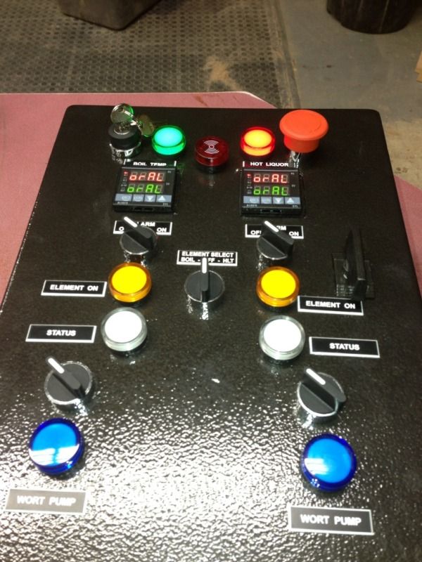
The 3 position switch seems like a simple solution but I'm not sure I like it aesthetically. The plastic (illuminated or not) switches that so many control panels on here use is definitely preferred.

See the element selector in this image. "HLT, Off, Kettle" -how do you do something like this?
7A1AA1BE-A9B3-47D6-AAE9-6157C48F3D2D-12984-00000711D2B8216A.jpg


Adam
 
I seriously appreciate the assistance, by-the-way.

-I'm noticing that so many of these diagrams seem to run pumps off of what seem to be just simple push-button switches and don't require a contactor... -This is because the pumps simply don't require too many amps right? -For some reason I thought that I'd have to install a contactor for each pump but that's only required for a BCS or Brewtroller-type system, isn't it?


Adam
 
If you really want to keep it simple and minimize cost, you could use a single SSR, single contactor, and single outlet to connect to the element you are using. Just unplug the MLT and plug in the kettle when you are ready to start the boil. Even easier would be the cooler MLT with no heating element and use the kettle to heat strike and sparge water.
 
I followed a link to the 3 way switch and it was a simple metal toggle-style switch.

Don't the plastic switches in the picture I liked to just control contactors?


Adam

I have the metal toggle style on my panel. It looks fine and works great. I'm used to seeing these type of switches all over aircraft cockpits, so I might be partial to them!
 
Note that plastic 3-way rotary switch can be wired to work just like a SPDT toggle switch. On the rotary switch you just connect the two Normally Open (NO) contacts together on one side and it functions like an ON-OFF-ON toggle switch. You can "enable/disable" contactors for two elements by connecting the 110v supply to one side of both NO contacts and connect the output from each NO contact one of the contactor coils.
 

Latest posts

Back
Top